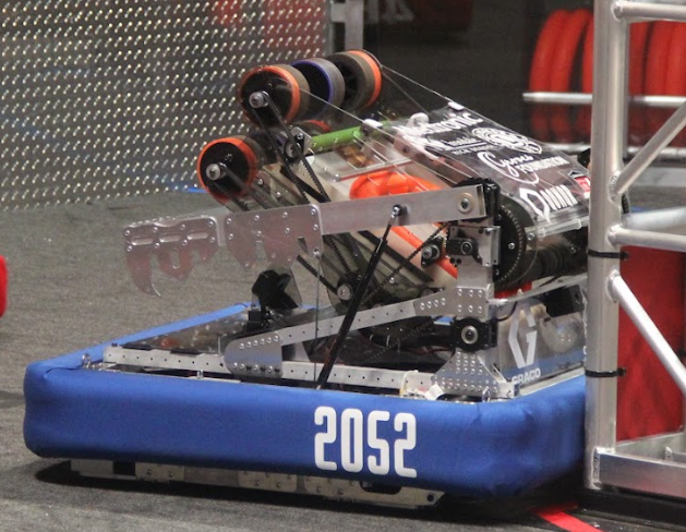
Every year, the FRC robotics team I am a part of needs to design a new, specialized robot. In 2024, I was in charge of the CAD/CAM for the entire robot and directly designed and iterated on many of its systems as well as manufacturing every plate on a CNC router. Below are writeups on a bit of the design and iteration process of systems that I created.
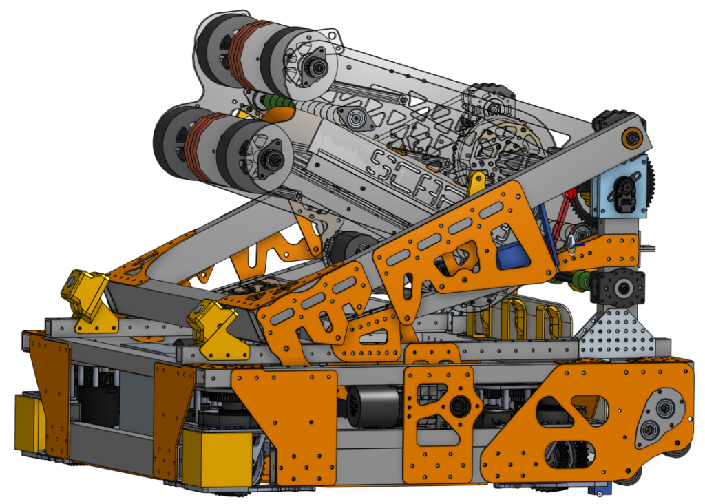
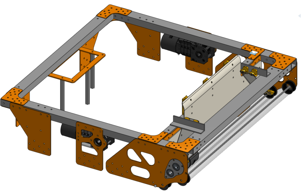
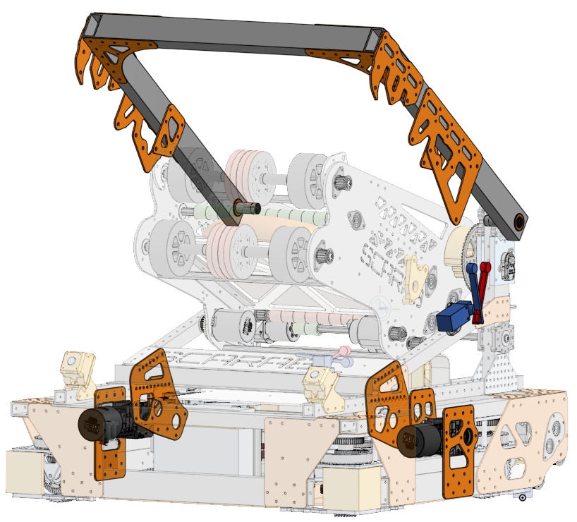
Chassis and Object Collection
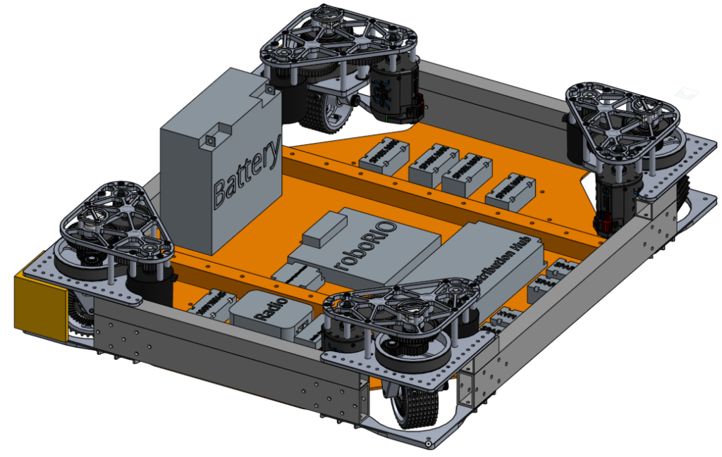
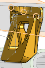
The chassis consists of two levels; a lower frame of extrusion connecting drive modules situated in the corners along with a belly plate to house electronics, and an upper frame that houses a collection system while providing solid mounting points for other systems. I designed the chassis as a whole in addition to designing and manufacturing the custom plates needed to assemble it.
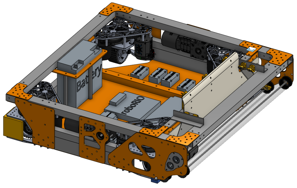
I designed the chassis with the collection system in mind, which is solidly attached to and even integrated into it. The robot was expected to drive at high speeds and be around other fast robots, so I made it robust to prevent major damage. I designed for multiple plates connecting the two frames in the corners to brace against multiple directions of impact and designed in extra extrusion to brace the collection system and belly plate, but despite this the chassis did take some damage during competition. The upper frame originally consisted of 1″x1″ box extrusion, which left the sides and back of the chassis vulnerable to bend in their unsupported middle sections. To combat this, this 1″x1″ was replaced with 1″x1.5″ and 1″x2″ on their side to prevent future damage.
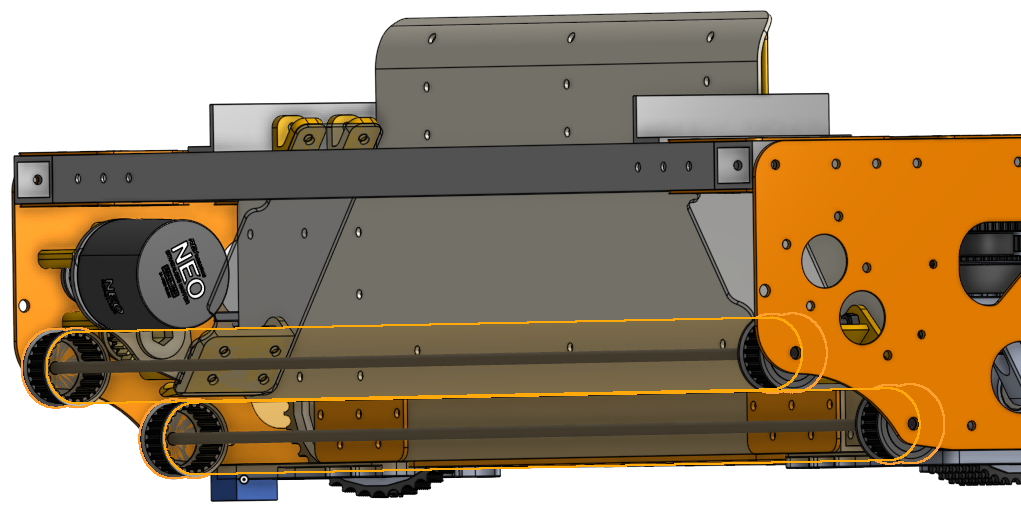
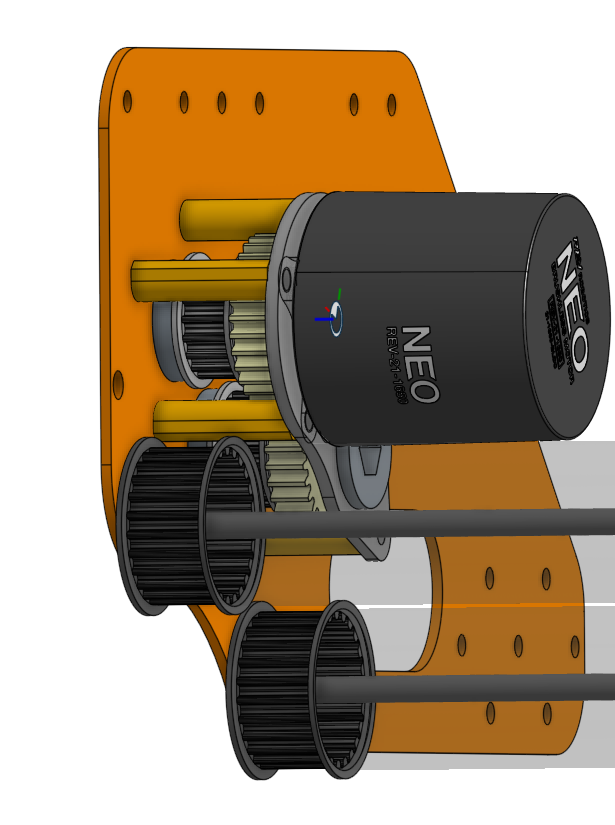
On the end of the chassis, the collection system consists of two dead axles spaced to provide compression and an upwards force. This is all belt-driven by a single motor and 1:1 custom gearbox, the placement and condensing of which determined how far the back of the upper frame needed to jut out from the chassis. In addition to the active components, a low friction plastic plate I added plastic diverters to guides and centers collected objects. Originally I designed these diverters as a single, large 3D-Printed piece; this turned out to be difficult to replace when damaged or to improve on, so I designed new diverters that combined small, lightweight printed parts with thin polycarbonate plates that were easier to service. These diverter pieces also serve to protect the drive motor and prevent objects from getting caught in the gearbox.
Pivot Structure
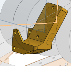
The pivot structure is where the both the climbing and object shooting mechanisms are mounted to and driven from. I worked on determining and finalizing the placement of its key features along with designing and manufacturing almost all of the custom parts that hold the structure together and give it function.
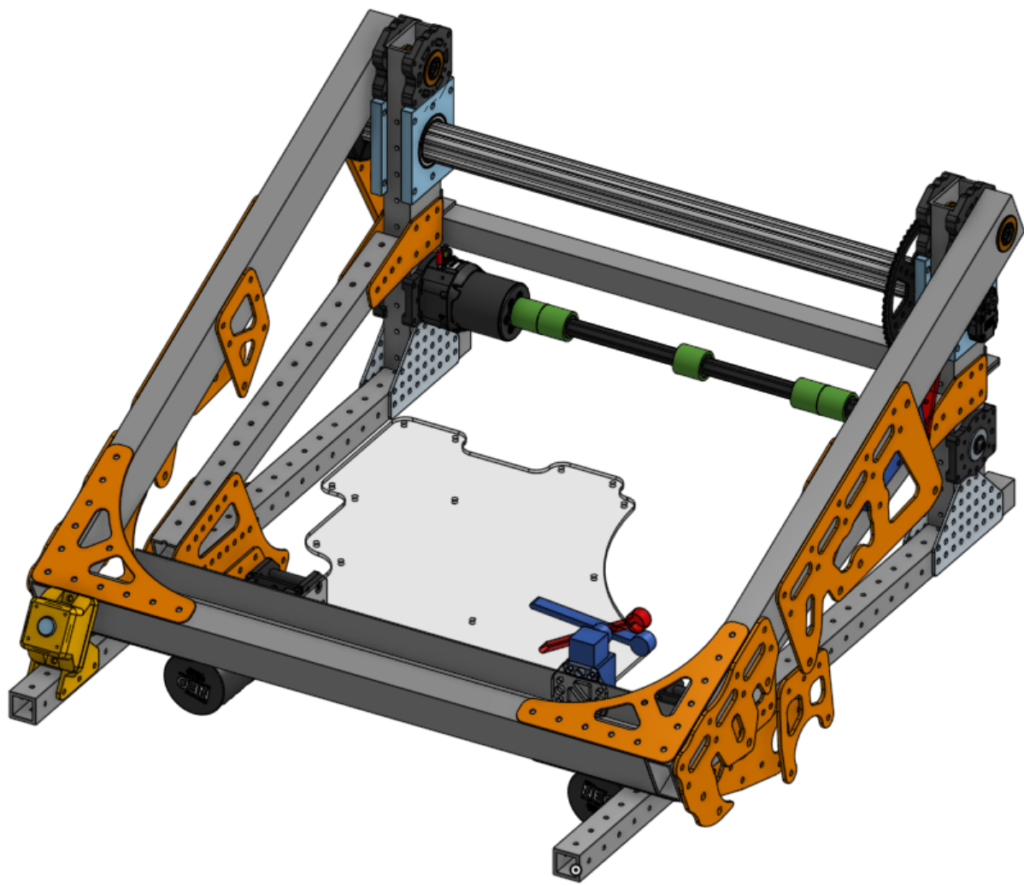
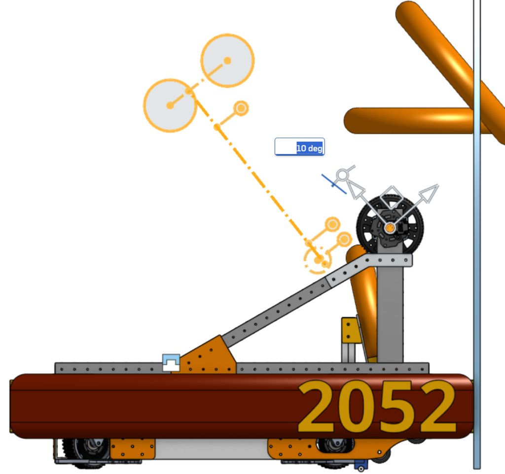
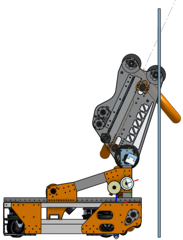
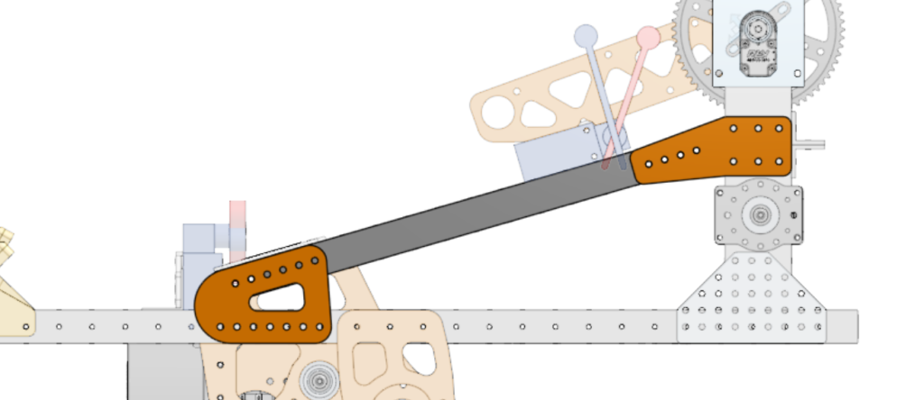
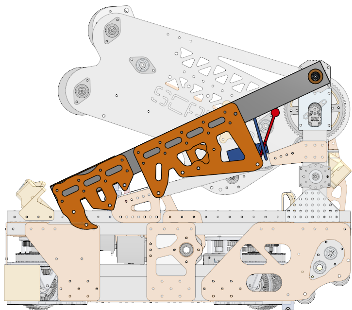
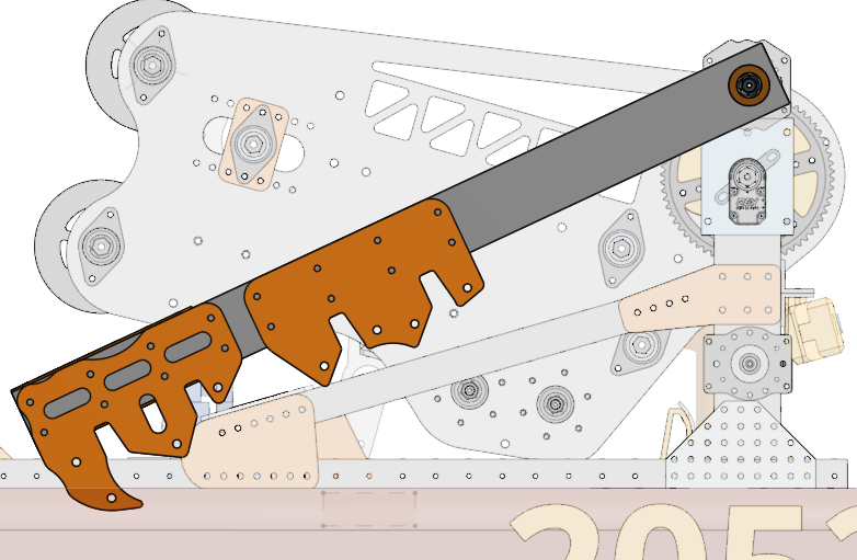
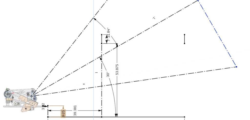
The overall shape of the structure was determined by the location of the main pivot arm that a shooter mechanism rotates around. Below are two prototypes to determine how high the pivot had to be to score a game object in one of the goals. I originally tried placing it higher up, however it complicated the path the object took through the robot and ultimately worked better lower.
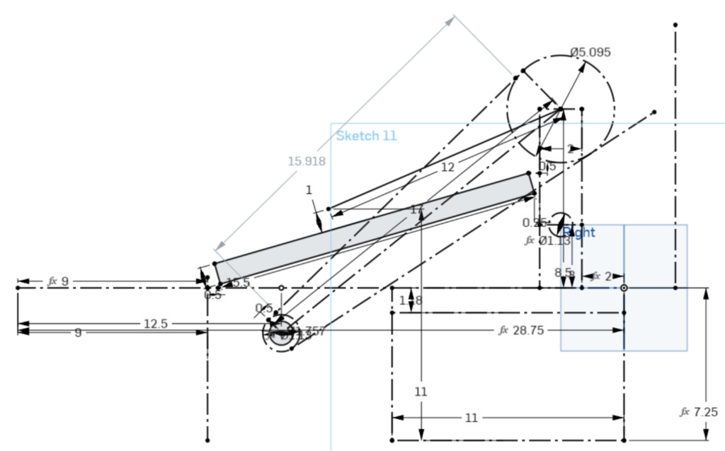
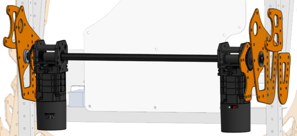
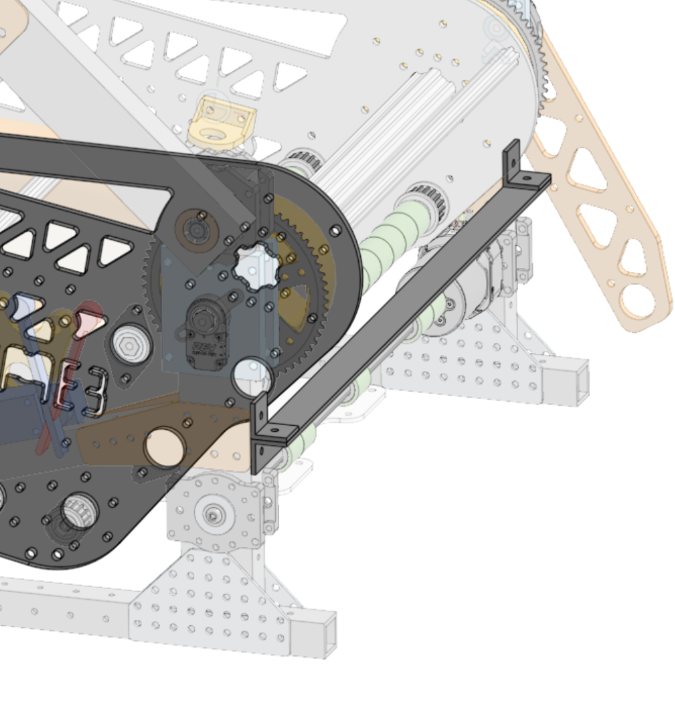
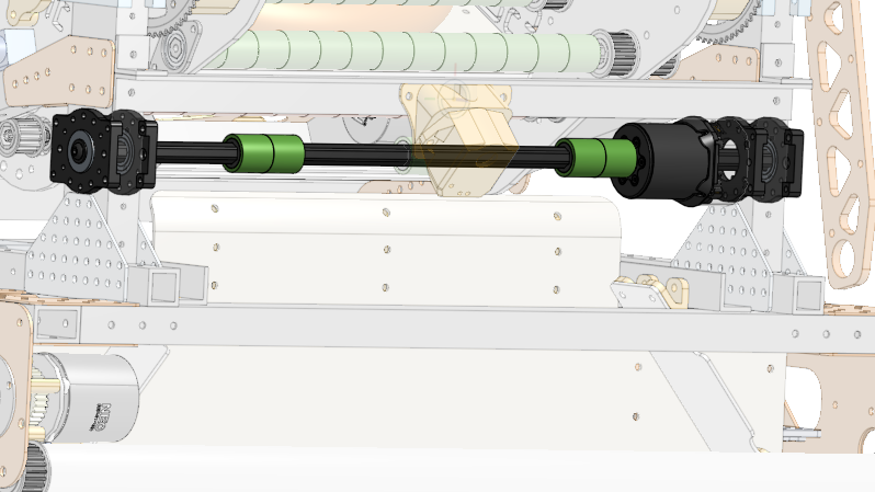
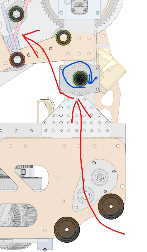
To drive this pivot arm, I used two motors driving a pair of tensioned chains. The tensioner attached directly to the chain and could not go around a sprocket, so I had to calculate the length of chain needed to achieve 100 degrees of rotation. With that length, I could find the center distance from the pivot that the driving shaft and its motors had to be placed. I initially tried mounting the motors to the chassis, however this used unnecessarily large pieces of aluminum while complicating how the motors mounted. What I ended up going with was attaching the motors to plates that mounted onto structural plates by bolts and 1″ spacers. They were spaced apart enough to fit the drive sprockets between them, and had mounting for the drive shaft of the climber mechanism. Unfortunately, these structural plates got slightly bent inwards during our first competition, damaging the climber’s drive shaft; to combat this I added bracing plates that exerted force in the opposite direction of the bend, allowing minimal bending in later competitions
The pivot arm also determined where I placed structural bracing. Due to the weight of the arm, I added side supports to brace the pivot. The location was determined by the only position where it could mount, being below the pivot. To strengthen the back of the structure horizontally, which had no fixed structure higher up, I added a length of L channel extrusion. I chose L channel due to the easy access to its inside walls allowing for the use of rivets as opposed to heavier and larger bolts, which wouldn’t have worked anyways due to space constraints. The placement of the L channel allows it to have some clearance to the arm when it is fully down, while brackets on either end allow it to be as secure to the frame as possible.
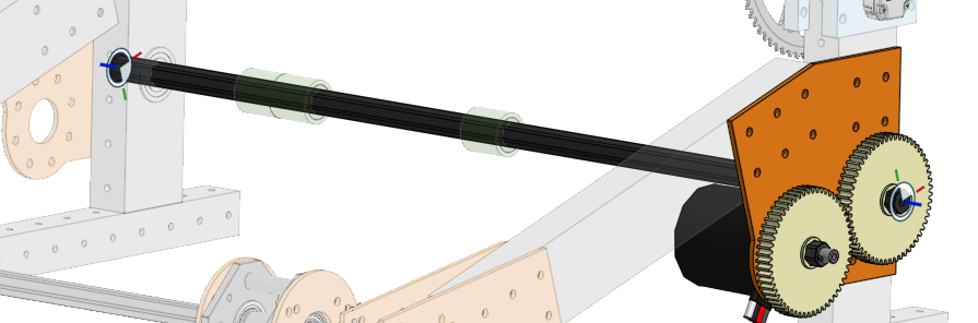
Another feature of the structure is housing a roller that deflects objects from the object collection system into the object shooting system. I ended up making it a simple shaft on a through-bore motor, itself on standard mounting plates to make it as simple and low-profile as I could. Originally, I designed it to use a custom plate and gearbox, however that would have added unnecessary weight and complexity.
Climbing System
The climbing system pivots at the top of the pivoting structure and consists of a toothed arm, a limit switch, a gas spring to drive it up, and a winch mechanism to pull it down. I determined the placement of the teeth, the limit switch, and the motors along with how everything is mounted. In its stowed position it is designed to be out of the way of other systems, and it rotates to reach up to almost 4′ high, designed to grab onto a loosely tensioned chain. To hook onto this chain, I placed teeth to grab the highest, near the highest, and lowest points where the chain reaches. I also modeled a slight hook on the end to both aid in grabbing the highest location of the chain and to catch the robot if it was climbing haphazardly. The original lower hook had an extra, lower position that made it more difficult to align, so I redesigned this hook to guide the chain into it even if grossly misaligned quickly. The climber arm also had no non-destructive stop to prevent overdriving, so I modeled a limit switch’s dimensions and used the existing structure to place the model where it could be actuated at the right climber position. I also took into account installing it as accurate as possible, so it is placed in an easy to align position. The switch required about 35 degrees of rotation to actuate, which was making it difficult to place where it both wasn’t in the way and was able to be actuated. To simplify this, I designed a small 3d printed part to keep the arm of the switch rotated slightly so that it would actuate with less rotation.
Camera Mounting/Placement
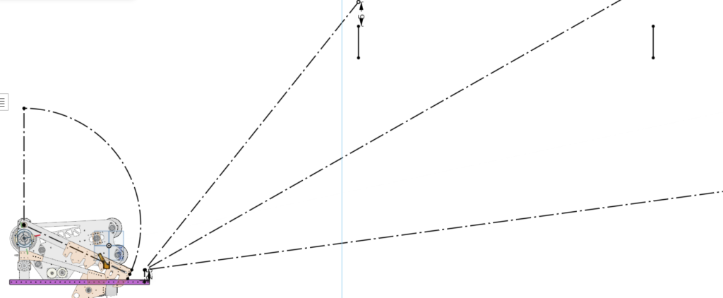
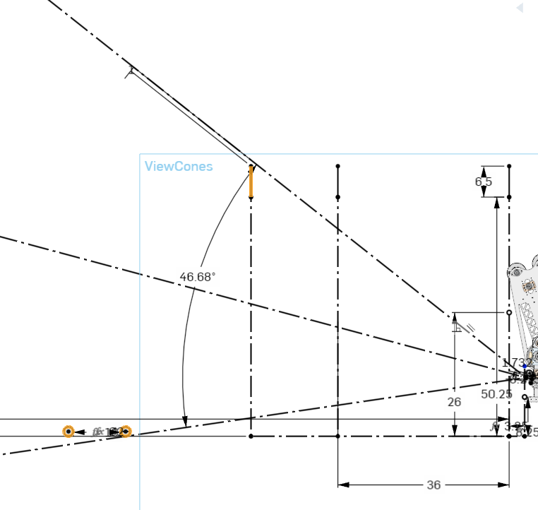
To determine where the robot was positioned and enhance our scoring capabilities, our code team needed some cameras to detect markers on the field. I worked with code to determine the field of view of available cameras and at what distances they needed vision, then designed mounts to attach the cases of the camera to available space on the pivot structure.
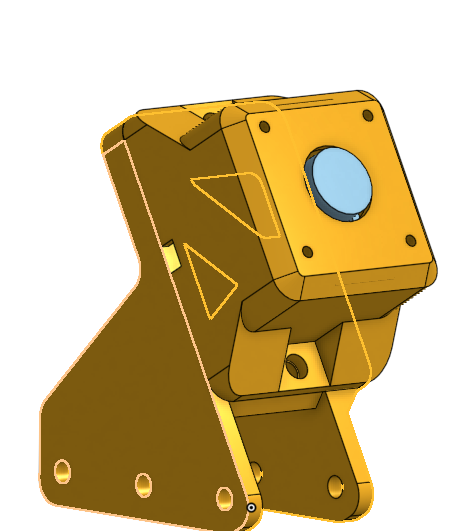
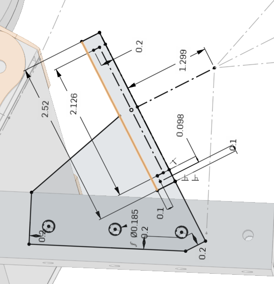
I designed two mounts, one for the front of the robot and one for the back. The front mount needed to see long distance, high up location tags; to model this, I sketched location markers at important distances from the robot, then added a cone emerging from the camera’s position to represent its field of view. Originally I tried creating a mount that was nestled a high up and far back position, however the camera’s view was blocked by surrounding mechanisms
When I figured out the position that worked best, it was low down in the corner of the robot. I made it low down for a couple reasons: I didn’t want to risk it hitting the climber arm, and I didn’t want the game object to get stuck on it if one were to fall onto the robot. to make sure that the former wouldn’t be an issue, I modeled in the arc of the climbing arm’s movement as a reference when designing the mount. After getting the specific location nailed down, I designed the mount to be able to be 3D printed flat on its face, without supports. I also added cutouts in the back of the mount to cut a small amount of weight and to provide a path for wiring the camera into the robot.
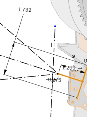
For the back mount, I had to work with some tight constraints. It had to fit within a 2″ deep space, which the camera case already took up most of. Alongside the space constraints, I tried to get the camera to see both a target 4′ off the floor and a object that was on the floor, which made the camera ineffective at seeing both. That wasn’t much of an issue, however, since it didn’t end up being used.
Link to CAD document – Scarab 2024