There’s a tradition on my high school robotics team where students get gifts for our adult mentors to give them at our end-of-year banquet. This chassis is one of two I made my last year on the team, and easily the one I’ve put the most time into. After all, it’s for the mentor that helped me learn to design mechanisms in CAD and who suggested I make this portfolio. He designed a small, easily 3D-printable robot chassis to serve as a platform for students to practice CAD design and coding a while back, so I decided the best gift I could give was an aluminum version of that chassis which ignored the entire point of the platform (he loved it, just to be clear). In the end this was a win-win, since it also gave me a chance to learn, show the skills I’d gained from the team, and machine parts that are more difficult/interesting than normal.
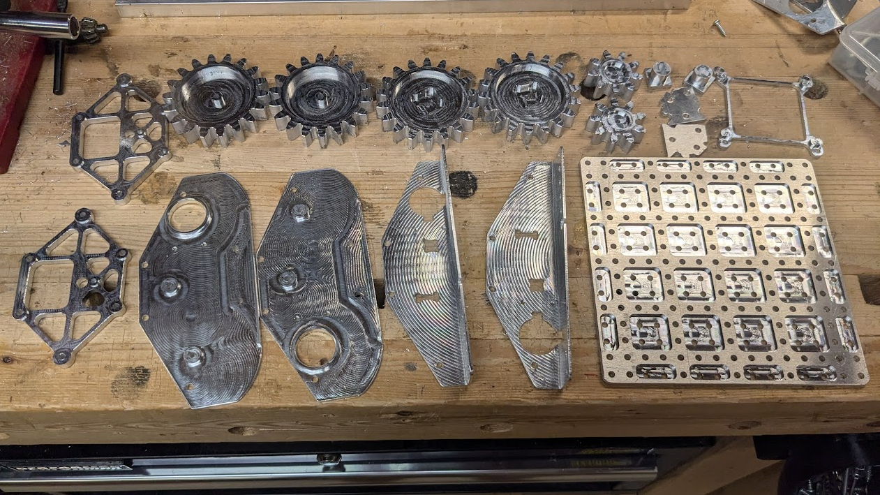
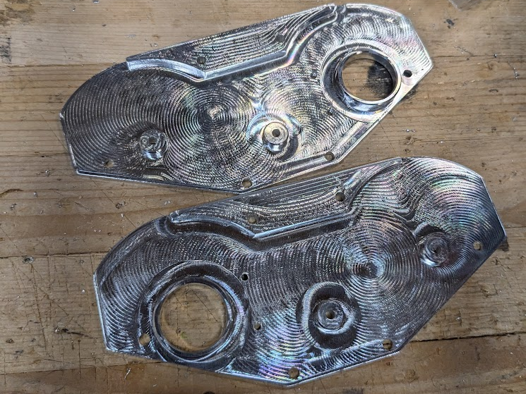
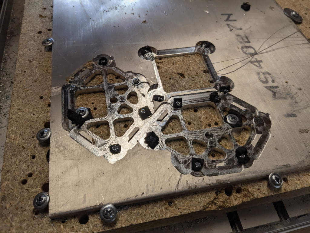
Quick disclaimer, since this is a gift that I’ve already given at the time of writing that means I only have visual aids that are digital or taken at various stages of the project. I couldn’t really get better ones if some weren’t the greatest, so please bear with me.
Adapting Model for Machining
Since the mentor who made the original chassis wanted people to easily print and design parts for it, I had an existing CAD model to work off of. My goal was to take this model designed with consideration to a 3D, additive process and make it out of a material I only have 2.5D, subtractive processes for all while keeping it as close to the original as I could. Luckily, there are some details that made this actually not all too difficult.
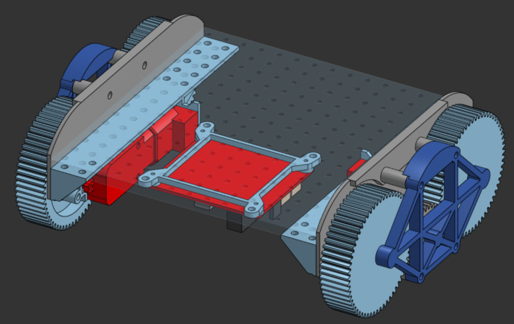
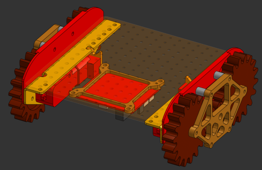
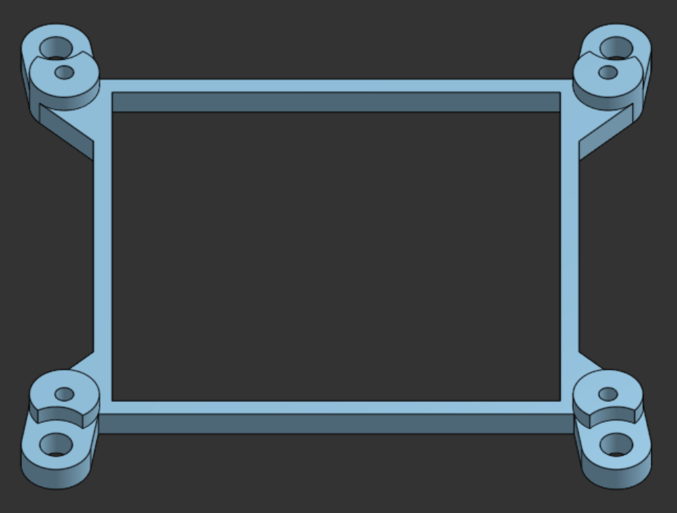
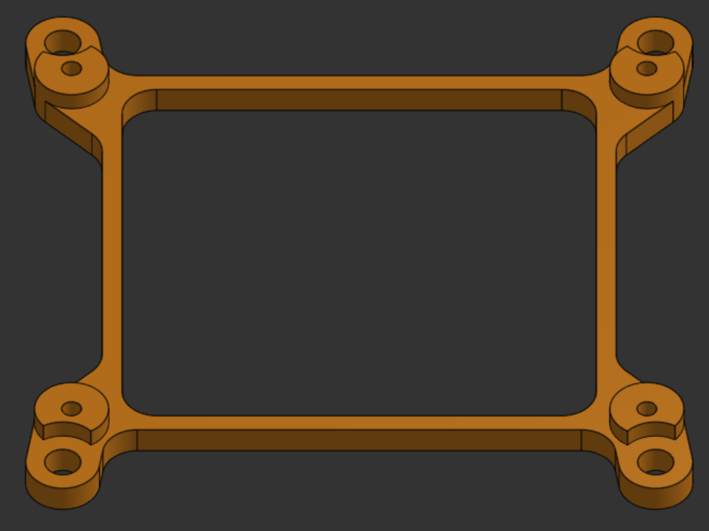
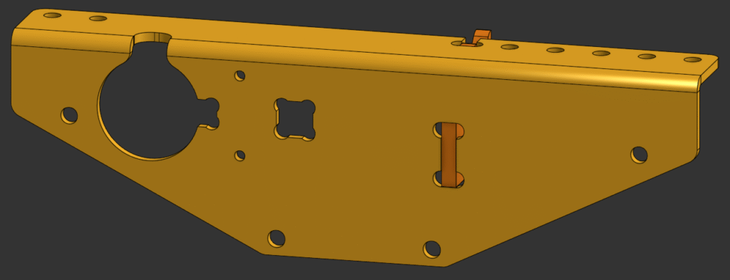
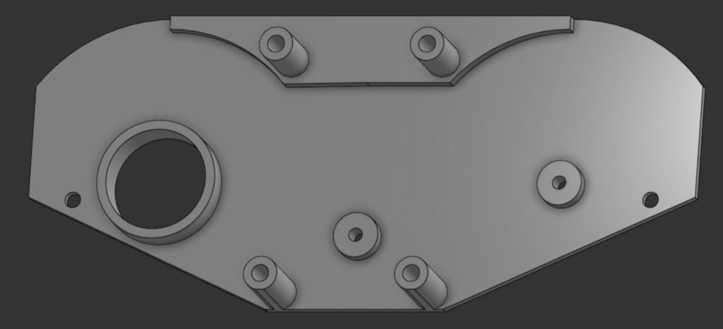
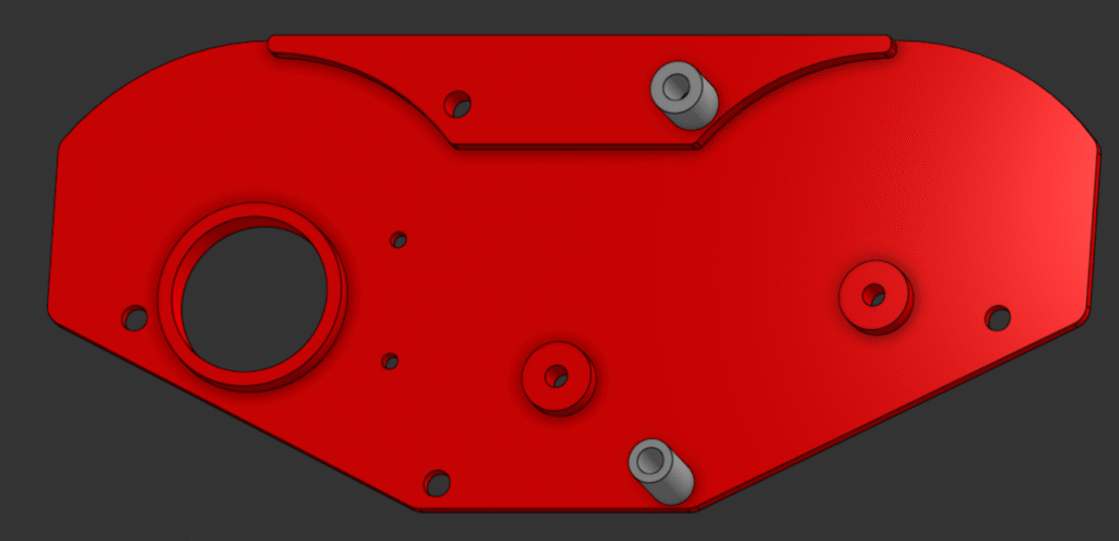
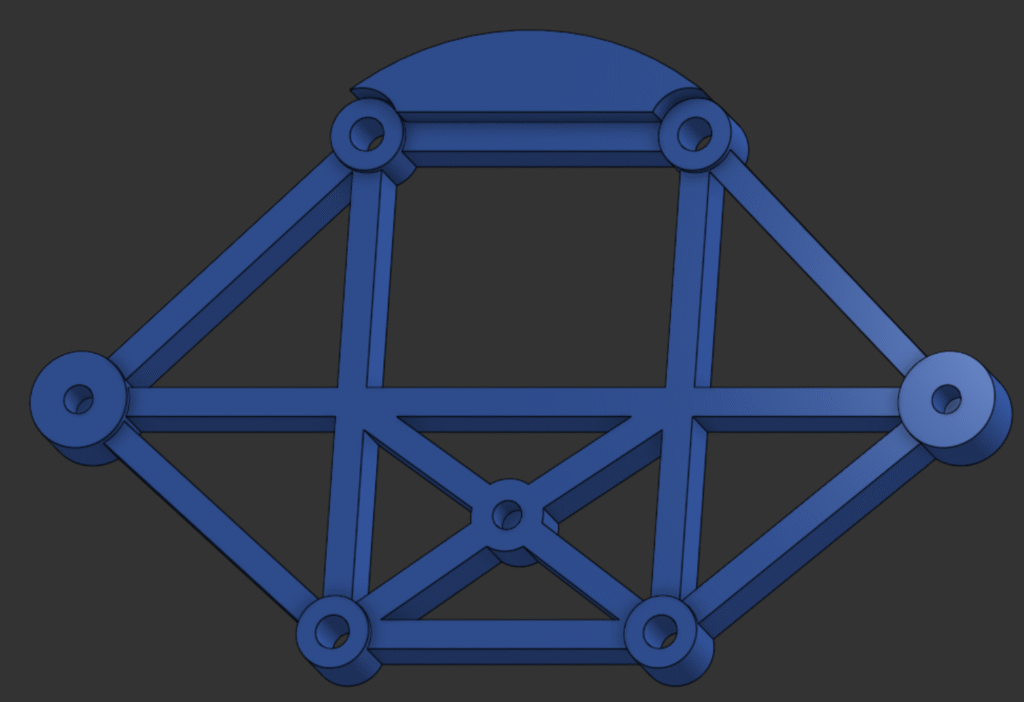
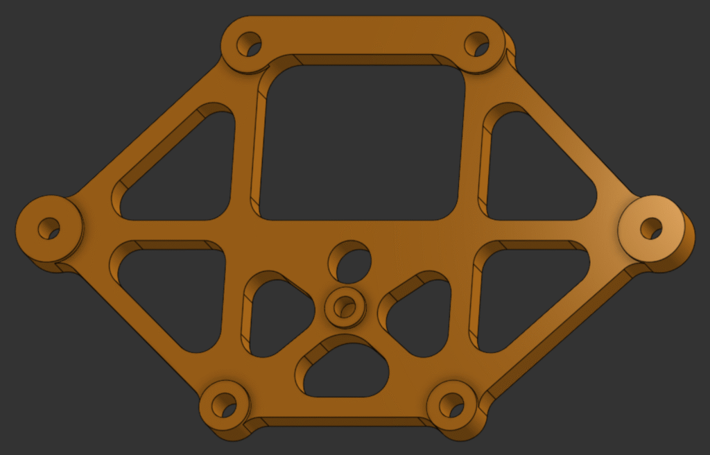
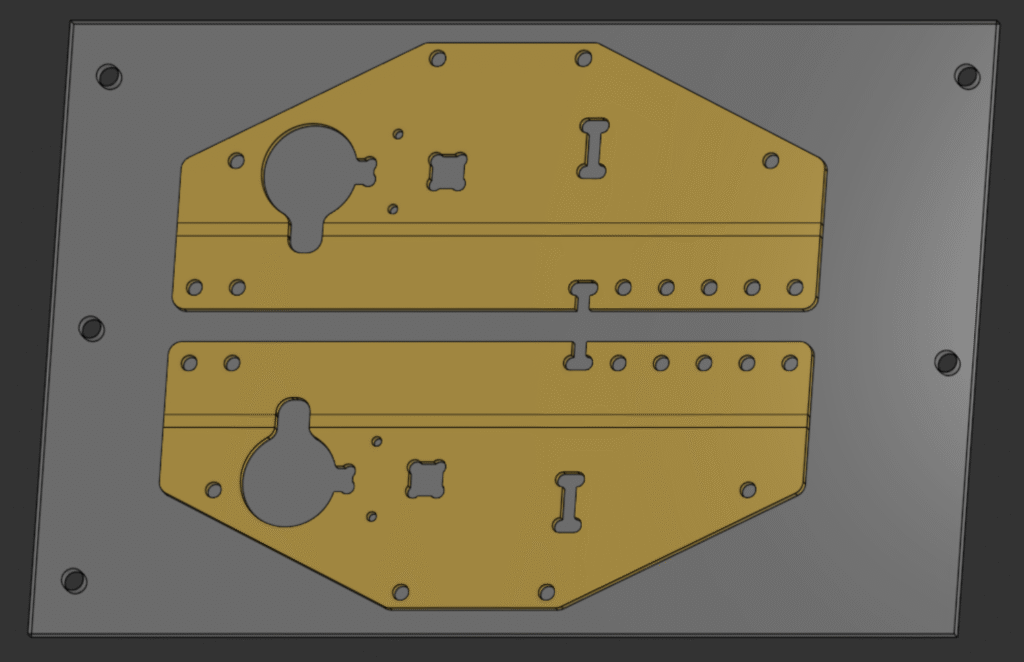
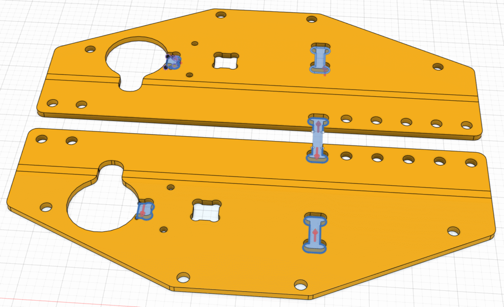
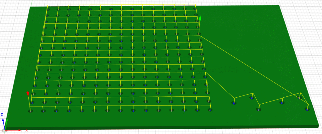
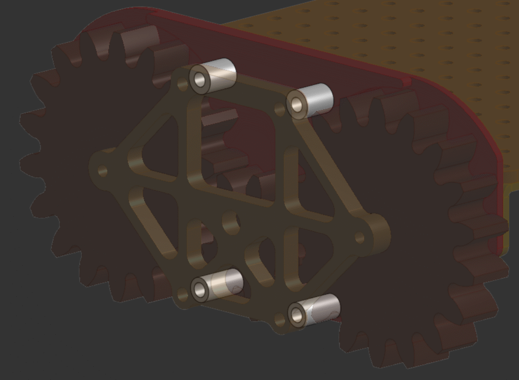
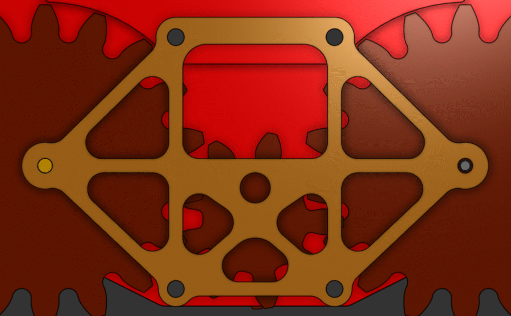
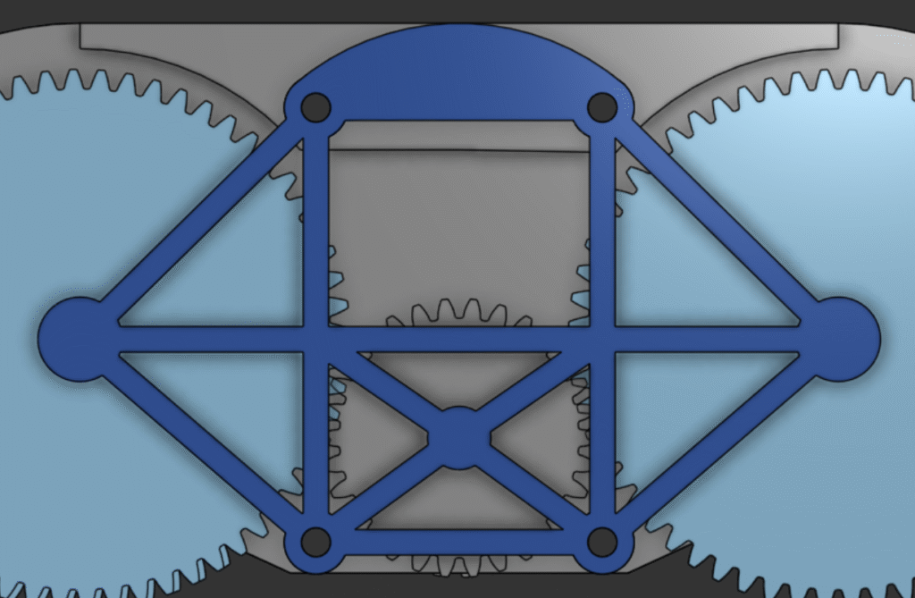
To start, all of the parts had flat sides to stick to the bed of a printer, which translated well to fastening them to a CNC router’s wasteboard. Additionally, everything was built to be bolted together to make the whole thing easy to assemble and work off of. I still had a decent amount of modifications to do, but everything was pretty reasonable. Below are the models for the original chassis (blue) and the modified-for-machining one (red) as a visual of the extent of my changes. To see a bit more detail, I made the big baseplate part of each transparent.
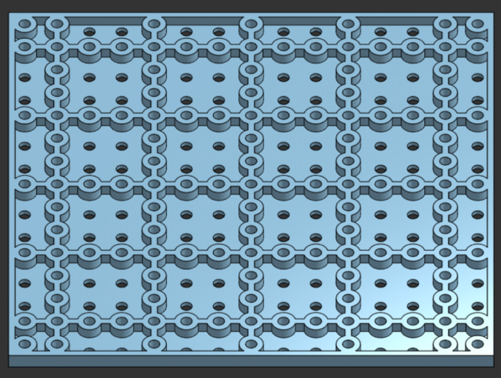
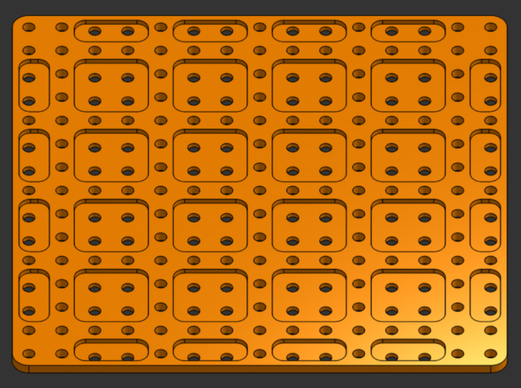
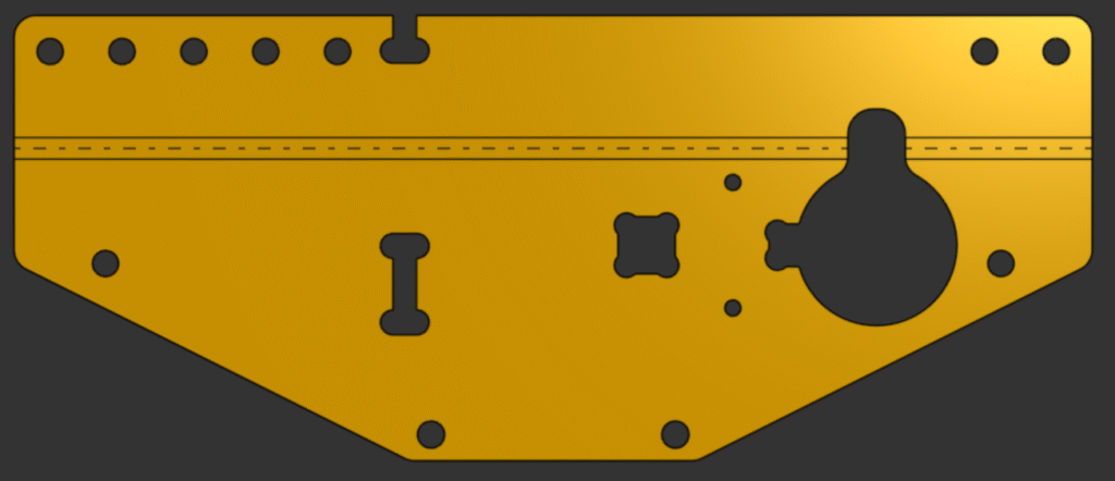
Speaking of the baseplate, it was pretty easy to modify. Flat sheets with holes in them are the most basic thing to make on a CNC router after all. I did have the change the pattern on the bottom originally meant to reduce the amount of filament used; all of the indents between holes were too small to accurately machine, so I just replaced them with neat square pockets. Another change that I ended making on all but a couple parts was changing the thickness of the part, which was just to match the thickness of the material I had available to cut.
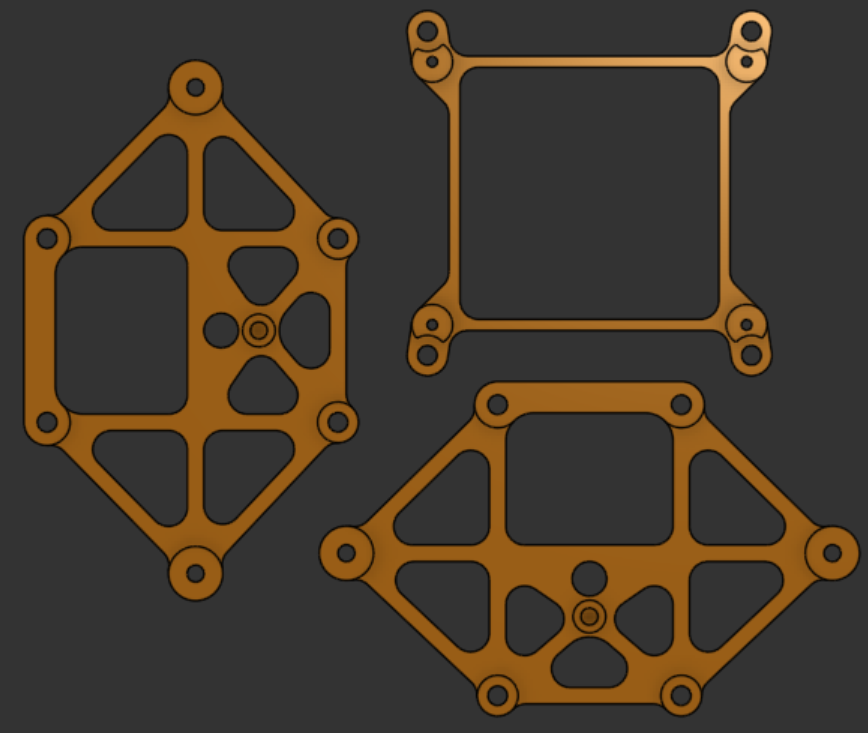
Attaching to the baseplate is an adapter between it’s hole pattern and that of the chassis’ control board. The two changes I made to it are also universal to all of the other parts, which are changing the hole sizes from metric to those of #6 bolts and adding fillets to all of the corners. My round cutting tools can’t cut any concave angle, so I always make sure to add a curve that’s slightly larger than the tool I plan on using; I also like to add a fillet to convex corners that I can physically machine, but that’s to reduce jerkiness on the router and most of the time just a love for smooth transitions between lines.
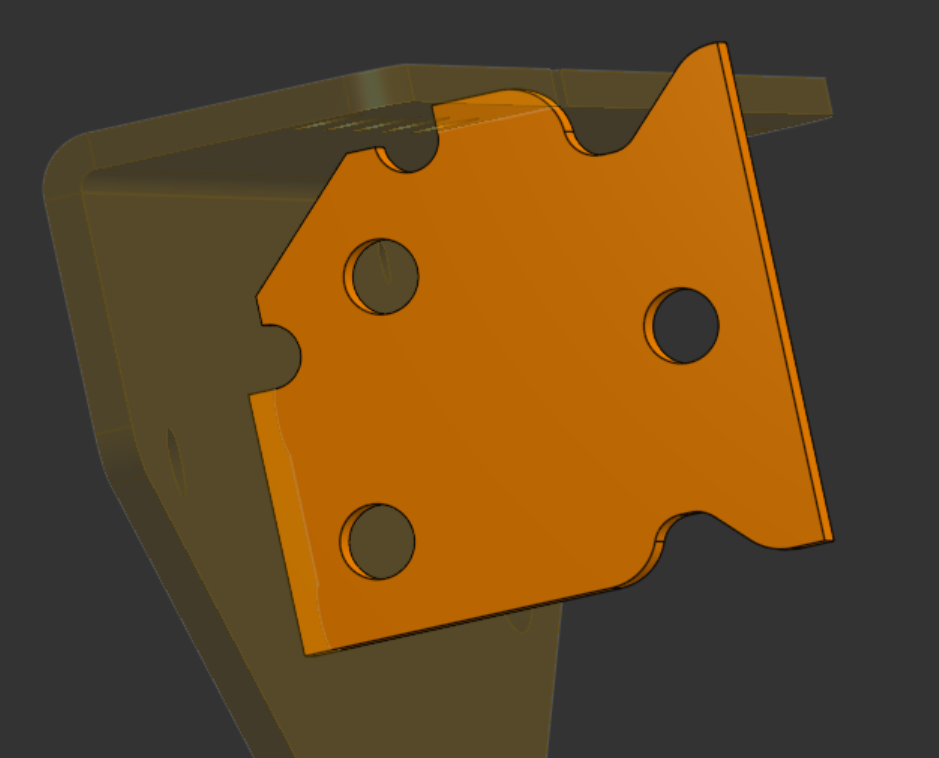
Radiating outwards from the baseplate, the next part to cover is a part that connects it to wheel-gear mounts, mirrored on both sides. This was the most difficult to adapt, since it had a lot of 3D elements easy to print but hard to machine. Rather than machine a large piece of billet and use multiple fixtures to get all of the features, I decided to redesign the part to be cut as a flat plate and bent. I scrapped anything on the model that couldn’t be a hole in the plate, except for a feature that the drive motors were meant to butt up against. This I turned into a separate part, as it was important to the functionality of the chassis and to the look of it. Additionally, to ensure that I could still strap a motor to this thing I added two threaded holes that match the mounting pattern of said motor as replacement for all the stuff I’d removed.
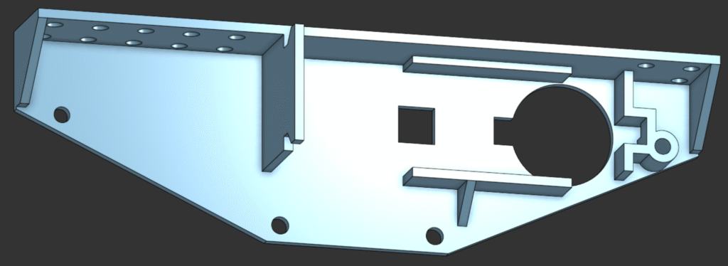
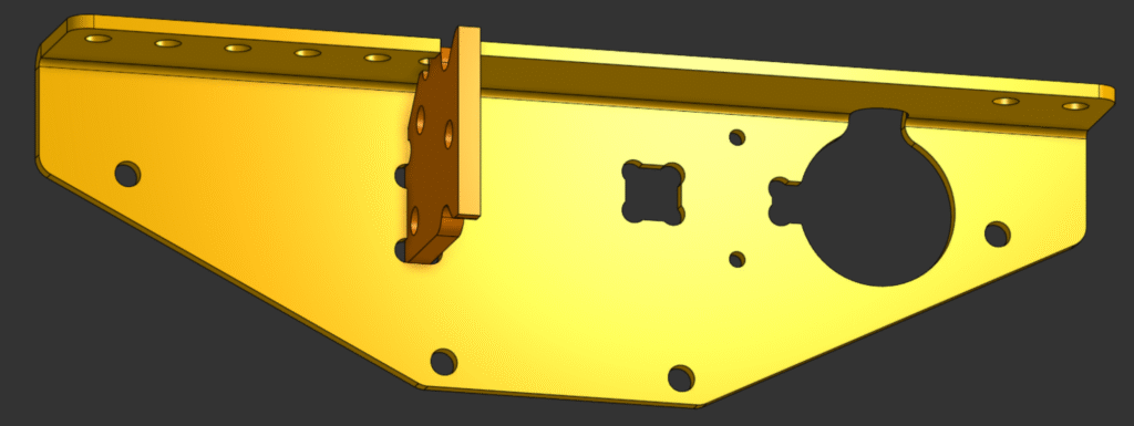
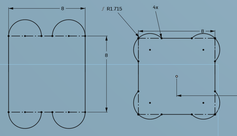
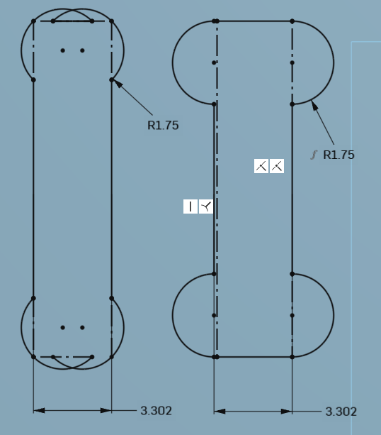
With all the nonessential 3D features removed and the part converted to a sheet metal model in Onshape, there were some other modifications to make. The big, circular hole in the part is for the motor’s shaft to pass through, but being so close to the bend meant that it could easily be deformed and unusable; to compensate, I added a cutout as relief for the hole that passes over the bend line. I probably should have added a relief for the small tapped hole also next to the bend, but overlooked it and ultimately just hacksawed a groove in before I bent it. In the existing cutouts for the motor, which originally had concave corners, I used a technique where I add a pocket around where said corners would be sp that my tooling can reach while still allowing a square object to fit snugly. For some slots added for the hardstop plate to fit into, I did something similar. Rather than do a cutout on the corners, I instead made these pockets tangent to the ends of the slot so that I would have a reasonable amount of material keeping the hardstop in place. Below is a flattened model of the plate for context, as well as some drawings showing both versions of a technique on both holes that hopefully help my application and explanation make sense.
Going back to the hard stop, there were some elements I designed into even such a small part that I’d like to share. Keeping in mind that my smallest cutting tool for the CNC router is an 1/8″ endmill, I made the part out of nominally 1/8″ material and designed the slot to be that wide, plus a bit of tolerance. Additionally, I left space on the corner of the part to account for the radius of the bent plate and made sure that it didn’t go all the way through so that the bent plate could sit flush where it needed to.
The next part out from the baseplate is the gear mounting plate, which attaches to the bent plate and keeps the whole drivetrain together. One of the biggest and clearest modifications I made to it was replacing the spacers originally integrated into the plate with detached ones; a bolt goes through them anyways, so this functionally changed little. I also tweaked various outcroppings on the plate to be smaller, which later allowed me to use 1/4″ stock with less waste than the 3/8″ stock I’d have needed before.
Attaching to the gear mounting plate, the modified gear retainer plates didn’t need too many changes. The most striking one is the change in the lightening pattern, however that’s the same except with fillets on every corner to make the part machinable. Otherwise, I tweaked a few dimensions and removed the weird, non-essential curve at the top of the original part.
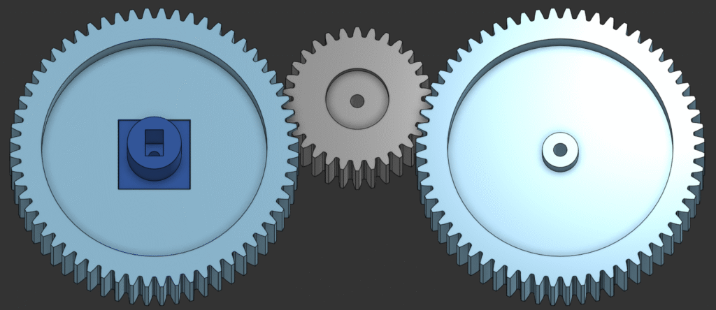
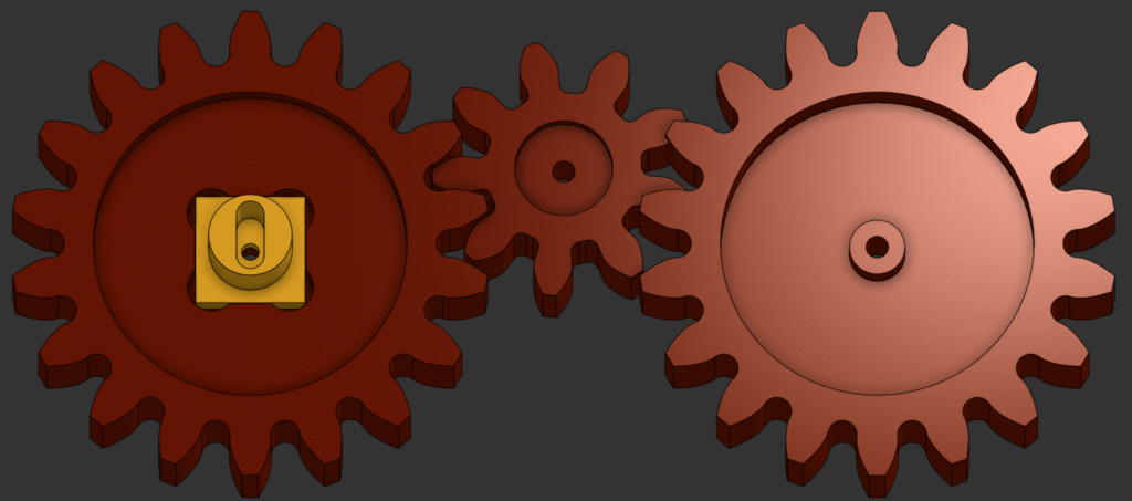
Also attaching to the gear mounting plates are, unsurprisingly, the gears that also serve as wheels. There were only a couple changes I had to make, mostly related to what I had available for manufacturing. For starters, the original gears and motor-adapter-shaft were all 3/4″ thick but the thickest stock I could get enough of was 1/2″, which dictated the thickness of the gears. I also had to change the pitch of the gears, as the smallest cutting tool I had available to make the space between teeth was an 1/8″ endmill. Other than those modifications, I just had to round out some corners to make features machinable and edit the depth of pockets that interact with other parts to reflect their changes.
Manufacturing
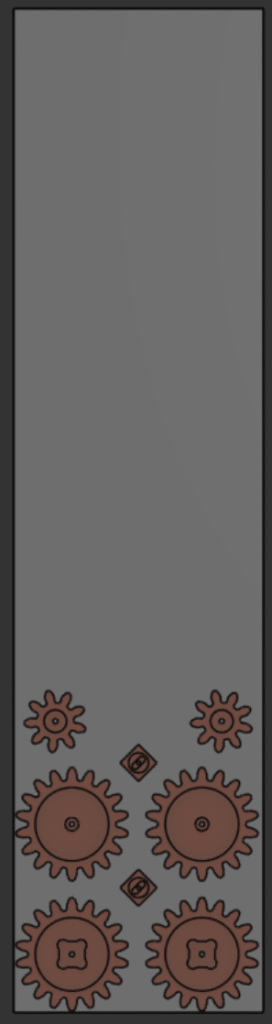
There were quite a few parts I needed to machine out of various thicknesses of aluminum, so to keep track of everything I started out with a list of what to cut with what stock along with the area that each part would take up. This let me figure out what I had enough of and the size of the plates/sheets I still needed to buy. After I got all the stock I needed, in Onshape I grouped part models that I’d cut out of the same stock and arranged them how they’d be machined. For some of these arrangements where I had limited space, I modeled the stock to make sure all the parts would fit.
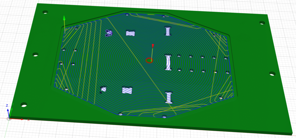
When I finished arranging parts, I imported each group into Fusion and started making toolpaths for the CNC router. The first part I machined were the pair of gear mounting plates, which needed a ton of material taken off. I ran a couple adaptive clearing paths to rough the base of the part quickly, then came back with more traditional operations to cut various features to the right dimensions. On first adaptive path I used, I left some material uncut around the posts that would later hold gears and the ledge of the plate to remove later; adaptive passes leave a poor finish, so I ran some small stepover passes to get a better one. This did leave me with a “skirt” around the edge of the part after I cut out the silhouette, which I removed with a “trace” operation that I ran full depth on the side of my endmill. It took some trial, error, and quite a few offsets to use this feature for the first time, but simulations in Fusion let me figure it out without destroying something.
The second part I machined was the pair of bent plates, which gave me an opportunity to dial in the 1/8″ 2-flute I’d need later for the gears. I didn’t have any tested tool data for it, but did have some for an O-flute of the same size that gave me a starting point; that one probably would have worked, but I wanted the strength and less-deflection that a higher flute cutter offered. Using the 2-flute on various pockets let me test what I had and make changes to get a better finish on a safer part, which in turn let me feel more confident with later parts.
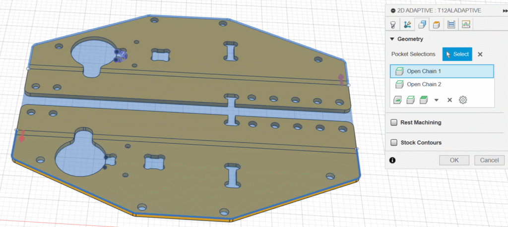
Some other things that I tried on this part were playing around with what I selected to cut in Fusion. First off, selecting individual sections of curves and lines lets you bound a region to cut which I used to cut two pockets on separate plates with the same toolpath, bridging the gap between them and lessening cut-time. Second, I wanted to machine a small part of a large pocket with my small tool for speed-reasons, so to select part of the feature I made a sketch in Fusion that bounded that region and used that as my selection.
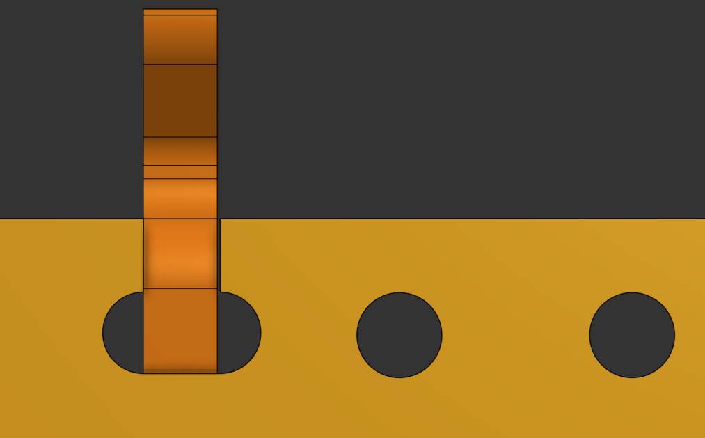
After those operations with the smaller tool, I swapped to a 6mm tool to machine the rest of the features. This included facing the two plates, where I used the same technique of using individual curves to bound a region as a selection of both parts. Rather than ramping down and facing each plate individually, this just ramped once and faced both at once. Once I’d finished off cutting the part with straightforward pocket and contour operations, I needed to mark up the part. There were a couple steps for me post-machining, like drilling and tapping small holes the router doesn’t have tooling to handle and bending the plate; to make them easier, I plunged a chamfer endmill where I needed to drill to create a dip helping me drill in the right place and afterwards ran it along the bend lines of the part, showing me where to bend when I took it to a sheet metal break at the robotics shop.
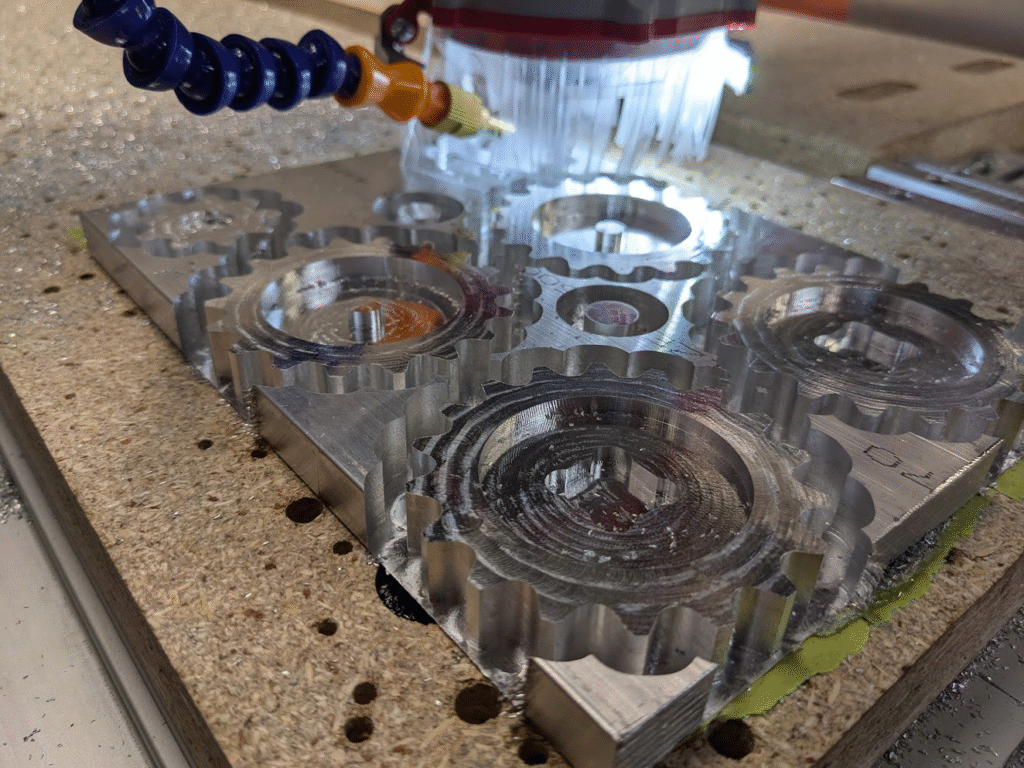
The most challenging part of this project, by far, was machining the gear wheels. I started with some pretty ambitious toolpaths that would work perfectly fine with most fixturing methods, but I planned on using tape-and-glue to maximize my stock usage despite the small surface area of my parts; not the smartest in hindsight. A couple details – like slightly-off cutting data generating too much heat and not being able to use too much coolant for fear of tape letting go – made roughing the gears difficult.
My toolpaths were designed with the fixture in mind. I started with multiple pocketing operations that I exported as one group, machining all of the features on top of the gears using a 1/4″ 2-flute for a nice finish. My next program roughed out the sides of the gears using the same endmill, taking off much of the material on each gear to lower the strain on the smaller, weaker endmill that I used to finish the teeth. Afterwards, I ran bore and chamfer operations to finish up all of the geometry I needed and nicen up the part. For each operation, I took small steps downward to limit the force exerted upwards by my tool on the material to avoid the tape releasing the parts. To help alleviate this, I left a little material on the bottom of each part that kept the whole piece of stock connected to try and maximize the surface area interacting with tape during roughing, which I then removed as I ran the finishing passes on the gears.
Everything worked pretty well, up until I started the roughing program; it took an hour to run what originally was supposed to take 20 minutes. As material got cut, the aluminum slowly started to heat up and, if it got hot enough, would come loose from the tape that held it. To avoid this I kept lowering the spindle speed to reduce the energy in the bit that could become heat, which forced me to lower my feedrate to not clog up the tool. Eventually I reached a decent equilibrium using a reasonable amount of coolant, but by the end of the cut I was running out of the isopropyl I spray onto the tool.
After the roughing was done, I had to take care of the operations with my 1/8″ tool. The bore I had to run was pretty jerky as it cut holes just slightly larger than the bit, but it didn’t make anything come loose. Before I continued cutting, I went back into CAM and split up my finishing program that did all of the gears at once into multiple doing just a few. I wasn’t sure if i would have as many issues as before, but that let me make changes in between parts. One such change was tweaking a height offset, as the first finishing program I ran that did the front two gears didn’t cut all the way through, which I fixed through some trial and error without waiting for another hour-long cut. Other than that, I didn’t have any problem with the rest of my programs and just had some deburring left to do.
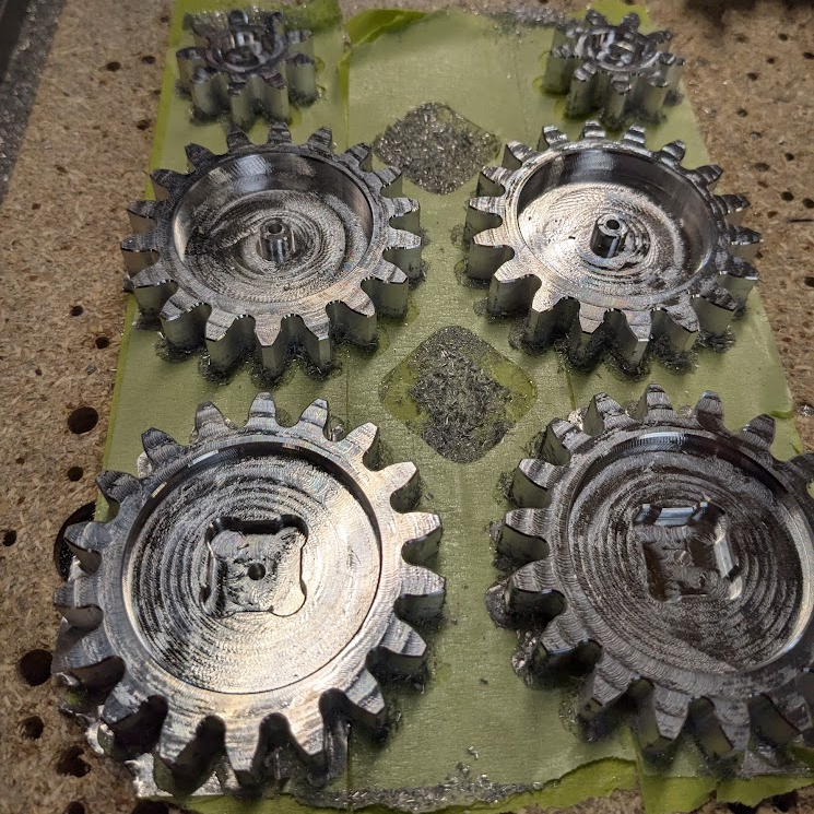
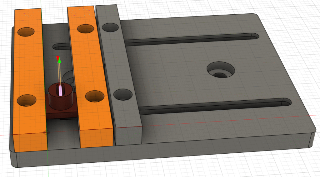
Well, I had to do a bit more than deburring to finish up this batch of parts. After I finished roughing, I was scared that the motor-adapter-shaft that I cut at the same time would come loose due to it’s tiny interface with the tape. This led me to take it off, as well as a couple of cutoffs that I didn’t want jamming into my tooling, and find a different way to add a slot to it. Going back into CAM, I made a setup where I held the part in my machine vise and used the 1/8″ tool to mill the last feature it needed. Most of the time I don’t need this fixture, but it’s a very useful one to have in reserve.
Next up, I had some 1/4″ parts that were easier but more complicated than most of the other parts. Each part had a couple levels to it, and I had to keep track of each of them. To make varying heights easier, the first operation I ran was a bore so that I wouldn’t have to swap out the tool I’d do everything else with. From there I use one tool and kept the same z-height across all of the operations, which means that everything should be accurate relative to all other features. Next, while the parts were all connected and the spindly one wasn’t, well, spindly and easy to mess up, I ran full-depth adaptive clearing operations to take care of all of the little and big pockets pretty quickly (in the video it shows a couple pockets cut after the rest, I missed a few the first time and had to add an operation after cutting those). These adaptive clears let me get good chipload on my tool while being smart enough to avoid tight spaces that cause wear, giving me the confidence to go full depth. Another adaptive path faced the gear retention plates, while some bores and pockets took care of milling cylindrical sections. I couldn’t find a good way to cut the top of the rightmost plate’s walls with the geometry of the part, so I had to make some sketches in Fusion and select them for a slotting operation that could cut in such a narrow area. The last thing I had to do on these parts was secure them to the wasteboard using some screws I put foam on to avoid scratches, then run a simple cutting operation on their silhouettes with a nice finishing pass.
Second to last, I had to work with some pretty tough parts. The larger, more solid parts were simpler but required more care to keep track of multiple heights while the spindly one was a challenge to fully machine. I started off with a bore to get all my holes into the parts, which I would use to hold them down when I cut them free with the last major operation. My strategy was to not do any tool changes so that I wouldn’t mess up my Z-zero, letting everything feature be the right height relative to the others even if my initial zero was wrong, and to machine as much as I could while the parts were securely held down. Since I had a lot of material to remove in a lot of different places, I opted to run full depth cuts knowing that my fixture could handle it (a nice change of pace after the gears). Adaptive toolpaths really helped out here, since I could get really good chipload without worrying about the tool getting 90 degree engagement while full depth. There were a couple times when I overlooked features, like some pockets that I milled after slotting as opposed to with the rest of them. Also, the geometry of the piece with the largest pocket forced me to either run a really weird and inefficient toolpath or get creative, which led me to sketching rectangles to select for a slot operation and fully machine the feature. To finish off the piece, I used the holes from earlier to tighten in screws to the wasteboard and ran a pretty simple cutting operation and drill-here-mark chamfer. For the cut, I made sure to leave some material as I was ramping for a finishing stepover to make the edge of the part look pretty nice.
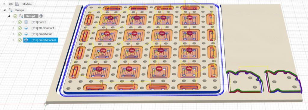
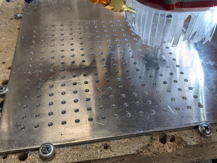
From the beginning of this project I knew that these last parts would be annoying to machine, not out of difficulty, but out of tediousness. The original baseplate had a ton of holes to allow for easy mounting of mechanisms, which meant that to be as accurate as I wanted I’d have to machine all of them. I used a boring operation with the 1/8″ 2-flute from earlier, then cut out all of the pockets and the outside of the plate with a larger tool. Oh, and I also used the 1/8″ endmill to machine the hardstops for the bend plate, since they were the same thickness as the baseplate.
Finishing Touches and Assembly
With all of the sheet-goods taken care of, all I had left to do was fashion some spacers and some axles for the gears, braze together a couple parts, and assemble everything.
I used some 1/4″ metal rod for the spacers, which are for connecting the gear retainer plate to the gear mounting plate. I cut the rod roughly to length on a chopsaw, then used a mini-mill to cut it squarely to the right size. Originally I planned on drilling out the center on a wood lathe set up with 2 chucks, but that was way too wobbly for me. Instead, I used the mini-mill as a drill press after popping the chunks of rod upright in a vise and locating the center manually.
Cutting the axles for the gears was even simpler. A hacksaw to some steel rod worked well enough since I didn’t need to be too accurate, and I cut one for each gear. I did have some problems attaching it, though. The designer of the chassis had the rods sandwiched between two plates, but in modifying the gear retainer plate I unknowingly removed one of the stops keeping them in. Fortunately, I could just braze some filler rod onto the plate as a cap and solve the issue. Probably should have caught it sooner.
I just had a bit of brazing and assembly to do after that. The motor hardstops had to be attached to the bent plates, which I didn’t do too cleanly but it held. Ideally, those stops and a couple #4 bolts let a drive motor be mounted on both sides but from what I’ve heard that won’t be tested, so the stop is there for looks anyways. What aren’t there for looks, for the most part, are the wheels; I tested that they rolled after assembly, and upon finding them locking up a bit I drove them with a drill. They work just fine now, although the motor drive shaft is a bit chewed up. Again, it’ll never drive and you can hardly see it anyways.
Reflections
This was a very fun project, and it gave me a chance to do a lot I haven’t gotten to do yet. For instance, I haven’t had an opportunity or reason to machine gears as thick as I did for the chassis, nor out of aluminum. I also don’t often have any plates machined with many 3D elements; this gave me an opportunity to try out new CAM tools and learn to use them decently well. As another bonus, I got to use new/less-familiar tools like a mini-mill, sheet metal break, 1/8″ 2-flute endmill, and a blow-torch brazing setup.
On top of learning/practicing fabrication skills, I also practiced the design and analysis skills related to different means of manufacturing. For example, I had to figure out how to make a part with a lot of features on different faces be made on a machine that can only machine flat-ish things, which meant figuring out what had to be kept, thrown out, or adapted. This also led into thinking about how much material would be wasted with different approaches, like if I had chosen to keep the integrated spacers on the gear mounting plates.
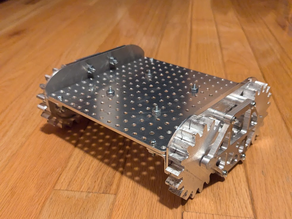
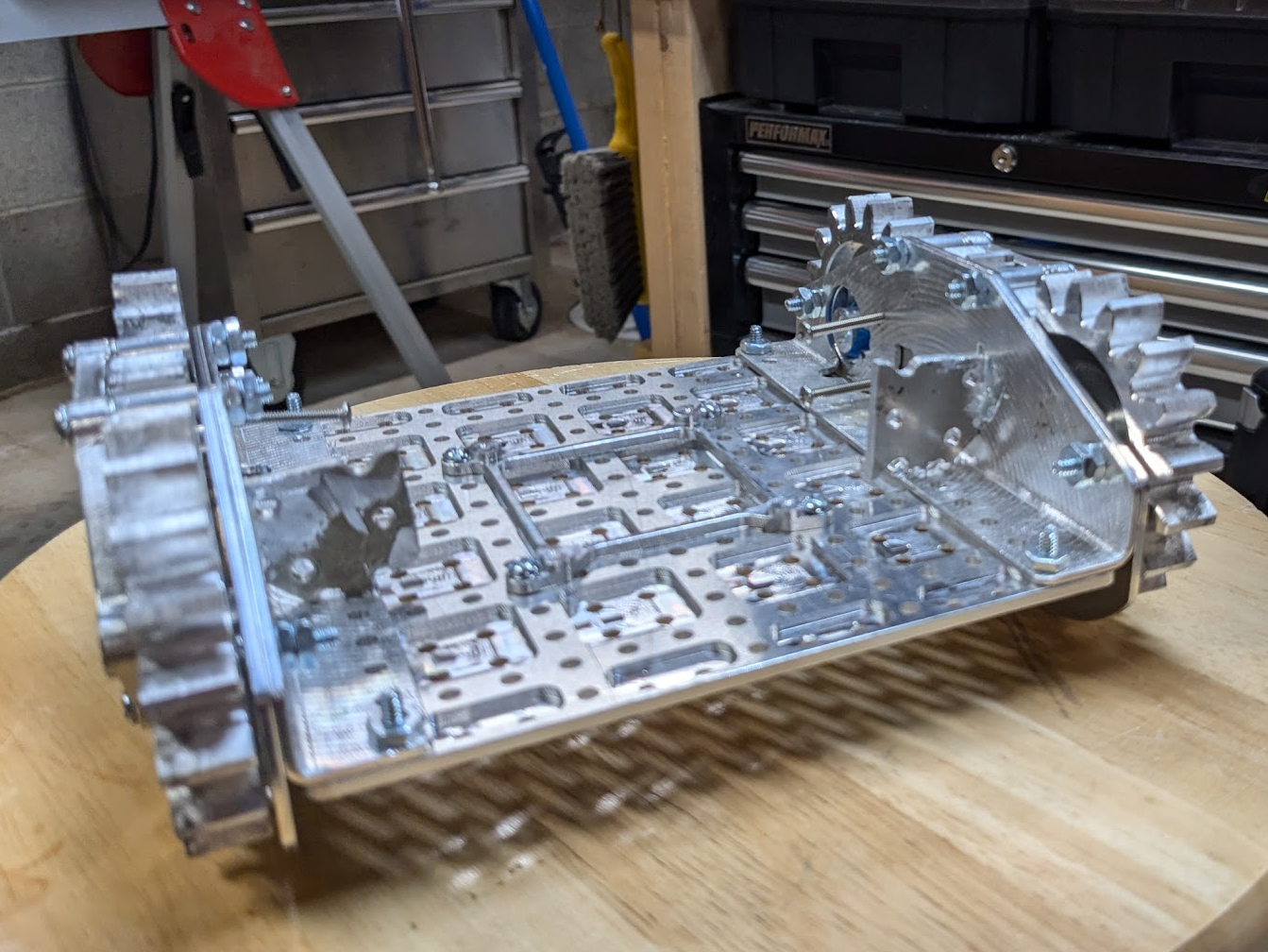
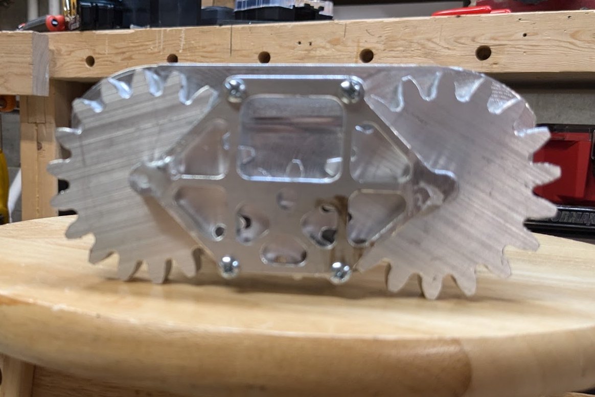
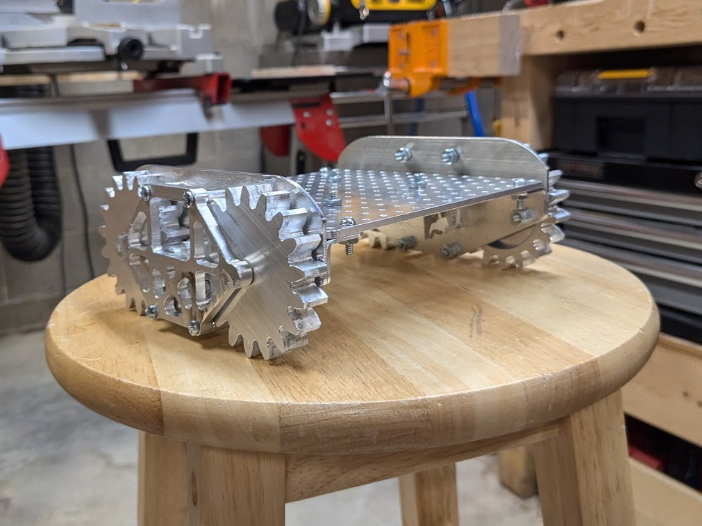
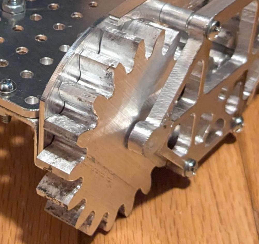
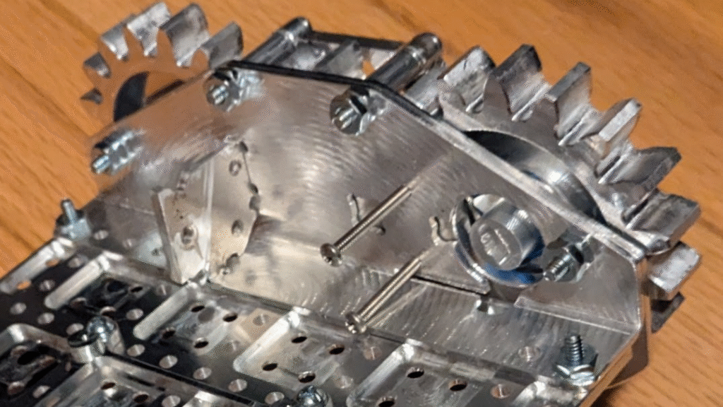
Some last minute glamour shots of the chassis: