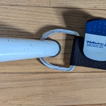
I’ve played the cello for the past 9 years, and I’ve had an amazing teacher for all of high school. As a thank-you to the energy and commitment that she puts into lessons, I wanted to make a gift using the skills I’ve developed alongside my instrument. I used the rock-stop model that she has for her classroom as a reference to build off of.
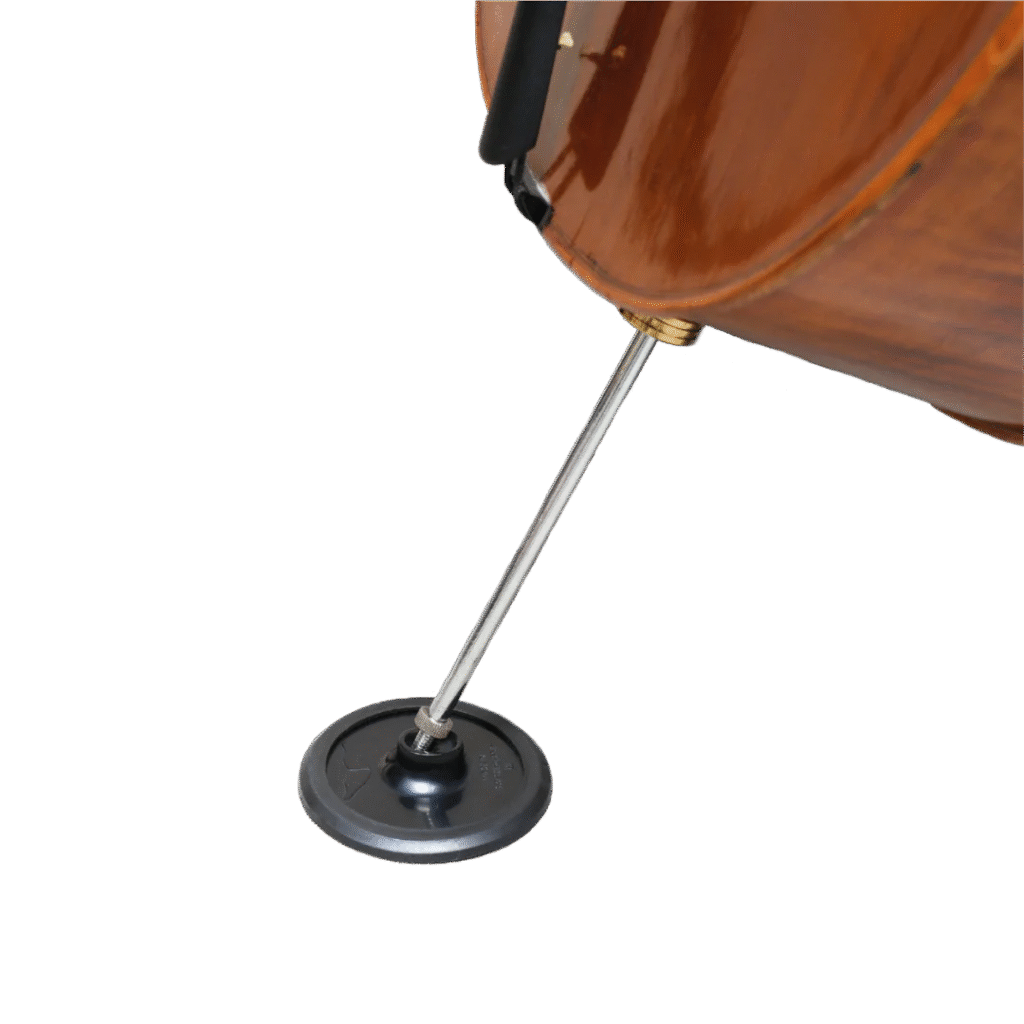
For some context on what a rock-stop actually is, it keeps the part of a cello that pushes against the ground–an endpin–in place. There are ones that rely on pure friction and ones that rely on a strap anchored to a chair, with both styles having their own advantages.

Ideation and Prototyping – Main Body
Version 1
To be as practical as possible, I wanted my rock-stop to have a strap yet work without it as a blend of the two styles. This decision made the project way more complicated but a much more interesting process.
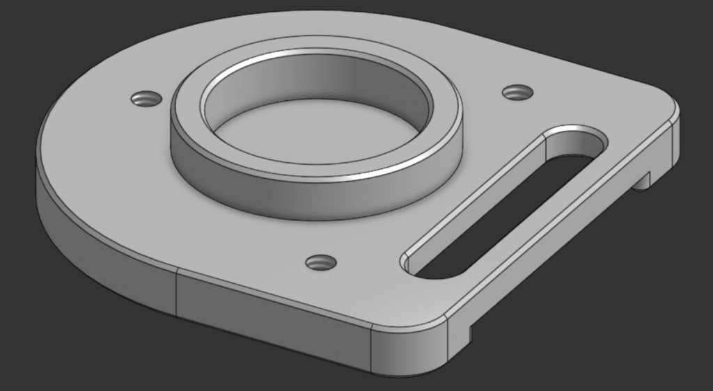
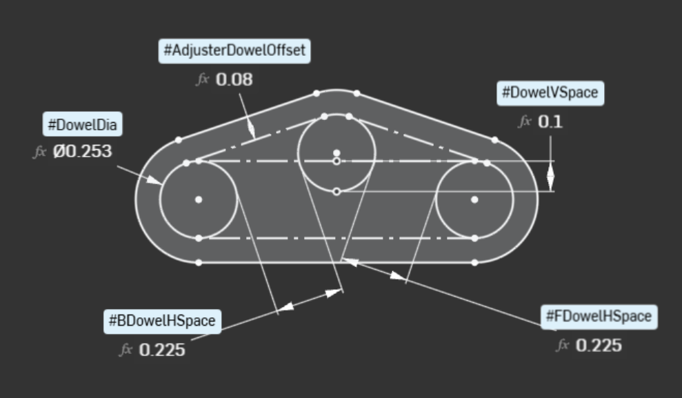
To start, I modeled a rock-stop off of guesses for dimensions to get a baseline for how deep the pocket for an endpin needed to be. Since I was working entirely off of temporary, guessed values, I made variable-driven sketches to make modifying dimensions easier later on.
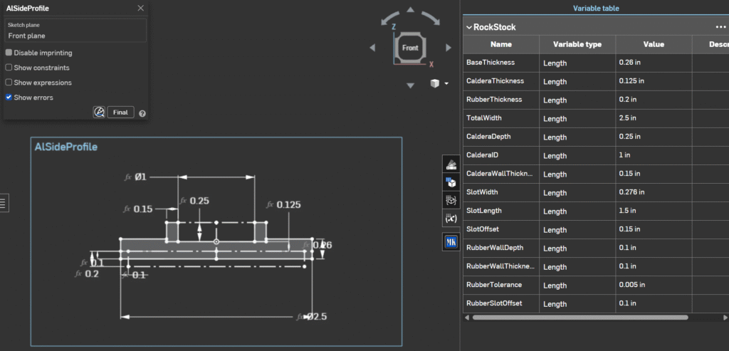
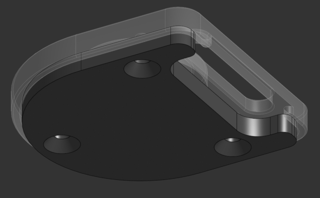
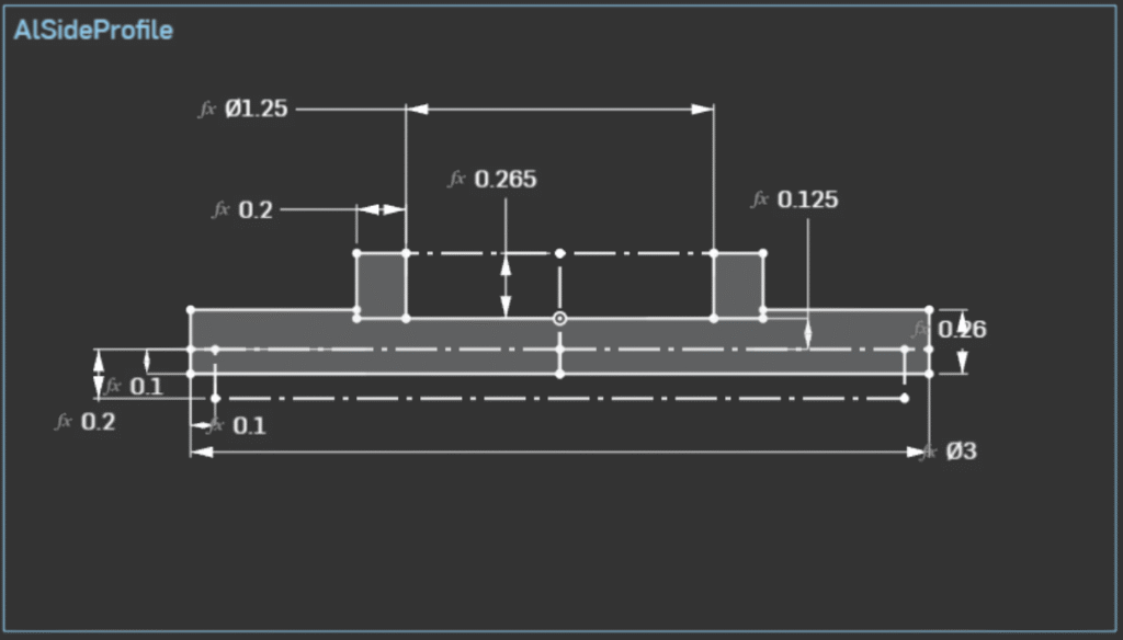
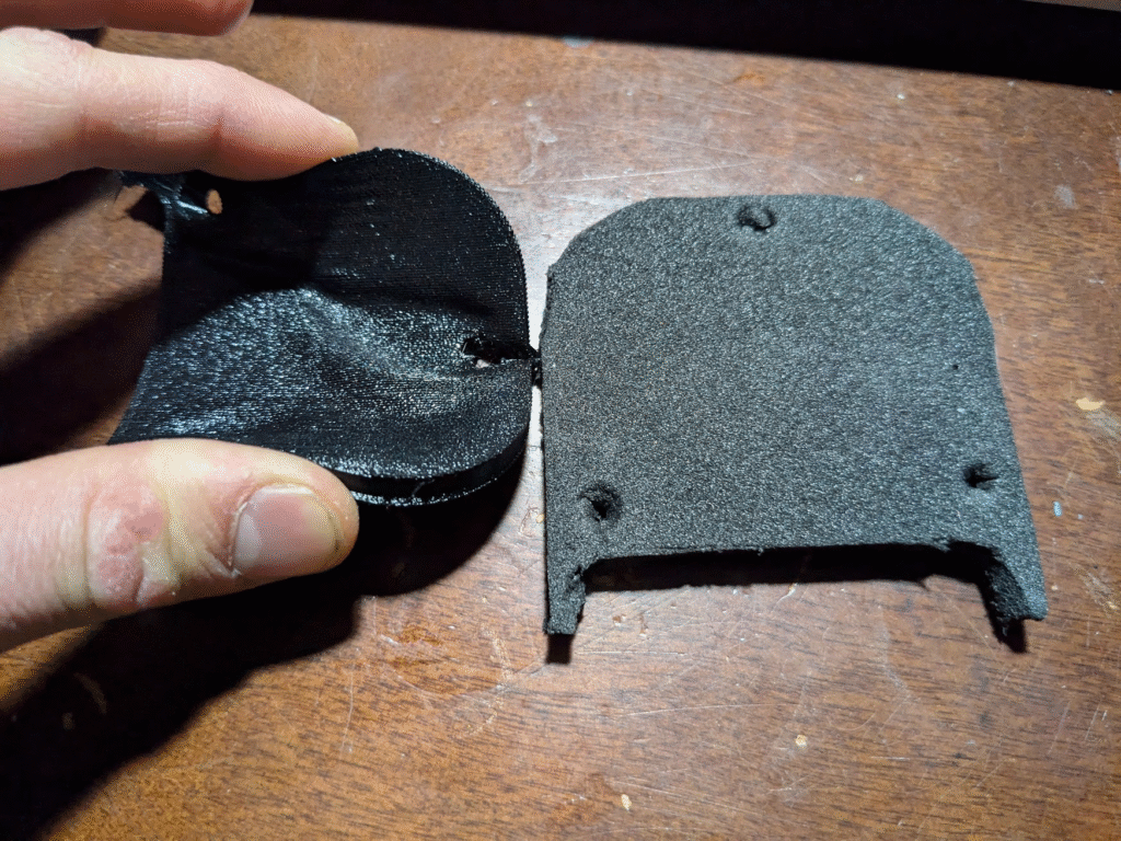
From the get-go, I was considering what elements the rock-stop needed. To allow it to work without a strap, I knew that I would need some soft material that the main body couldn’t be made out of, leading me to model a friction pad attached to the bottom. The most effective way I could think of to connect it was with bolts threading into the main body, and to make the assembly look nicer made it inset partially into the body. I really wanted to use 1/2″ aluminum for aesthetics and challenge, so I made sure that all of the geometry for the endpin-pocket and pad pocket fit within that height.
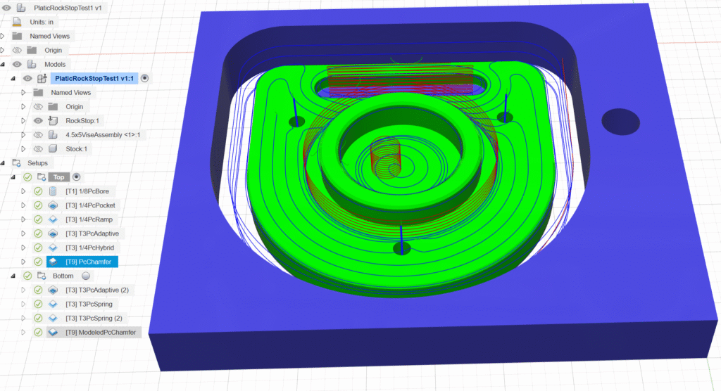
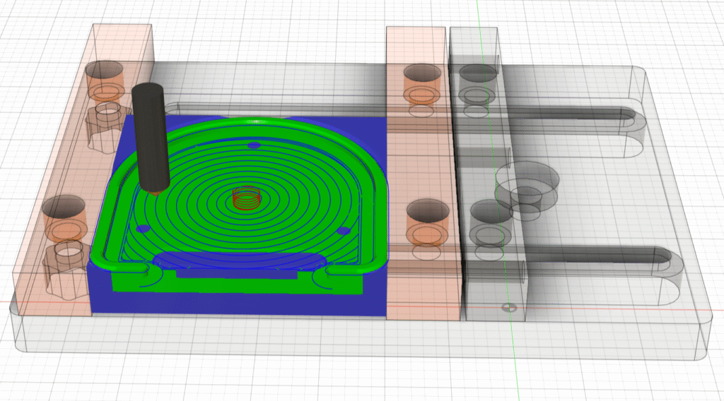
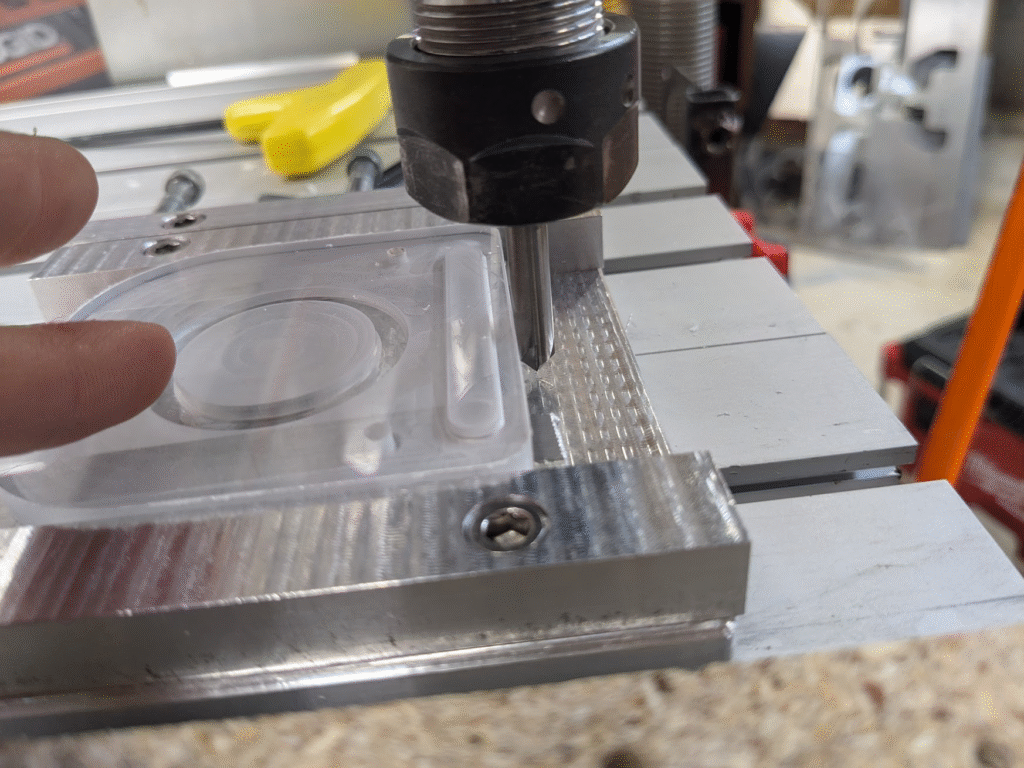
Eager to test what I’d made, I started manufacturing. First I 3D-printed the pad out of TPU filament so that it could easily compress, then machined the body out of scrap 1/2″ plexiglass so as to not waste aluminum. Since the part has elements on both its top and bottom, I had to make toolpaths for both sides of the part. I held down a large piece of scrap on my wasteboard, running programs to machine the top of the piece. For the bottom I had to toss it in one of the machine vises I’ve made, then pocket out where the pad goes.
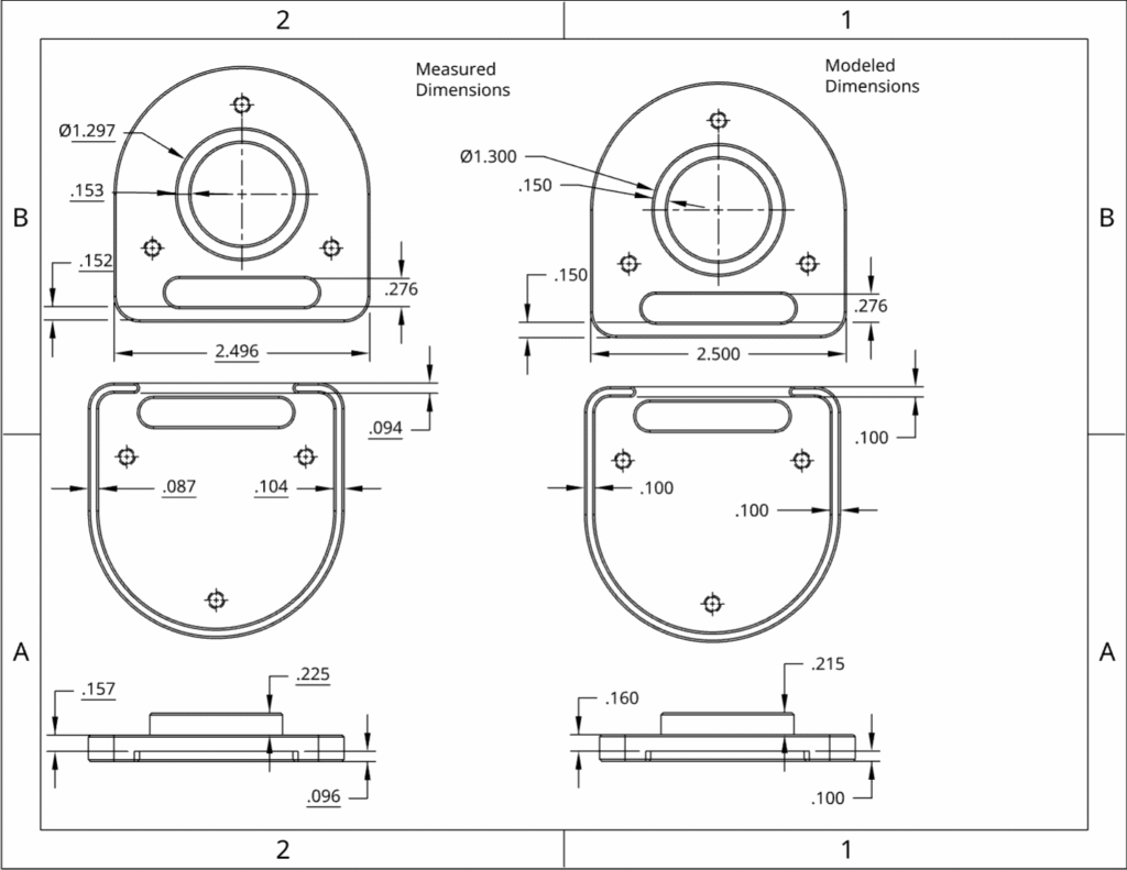
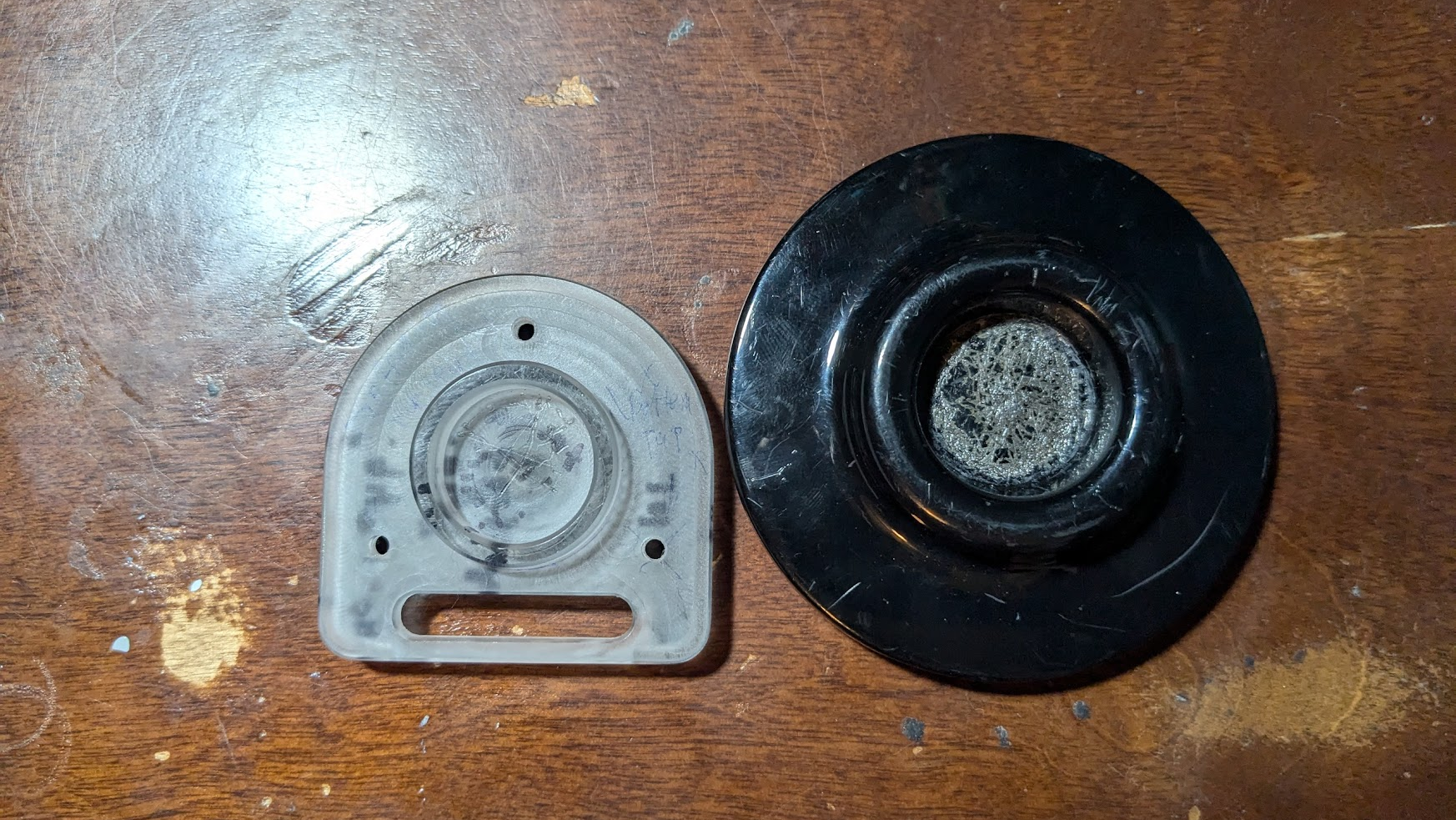
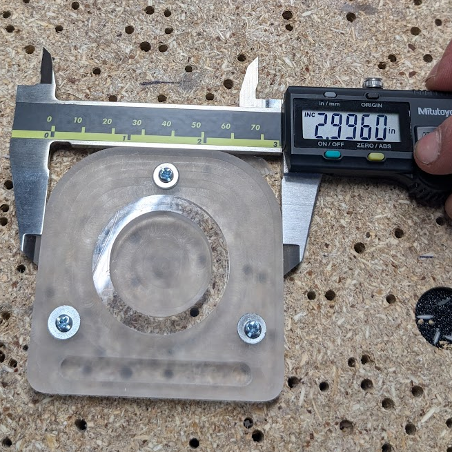
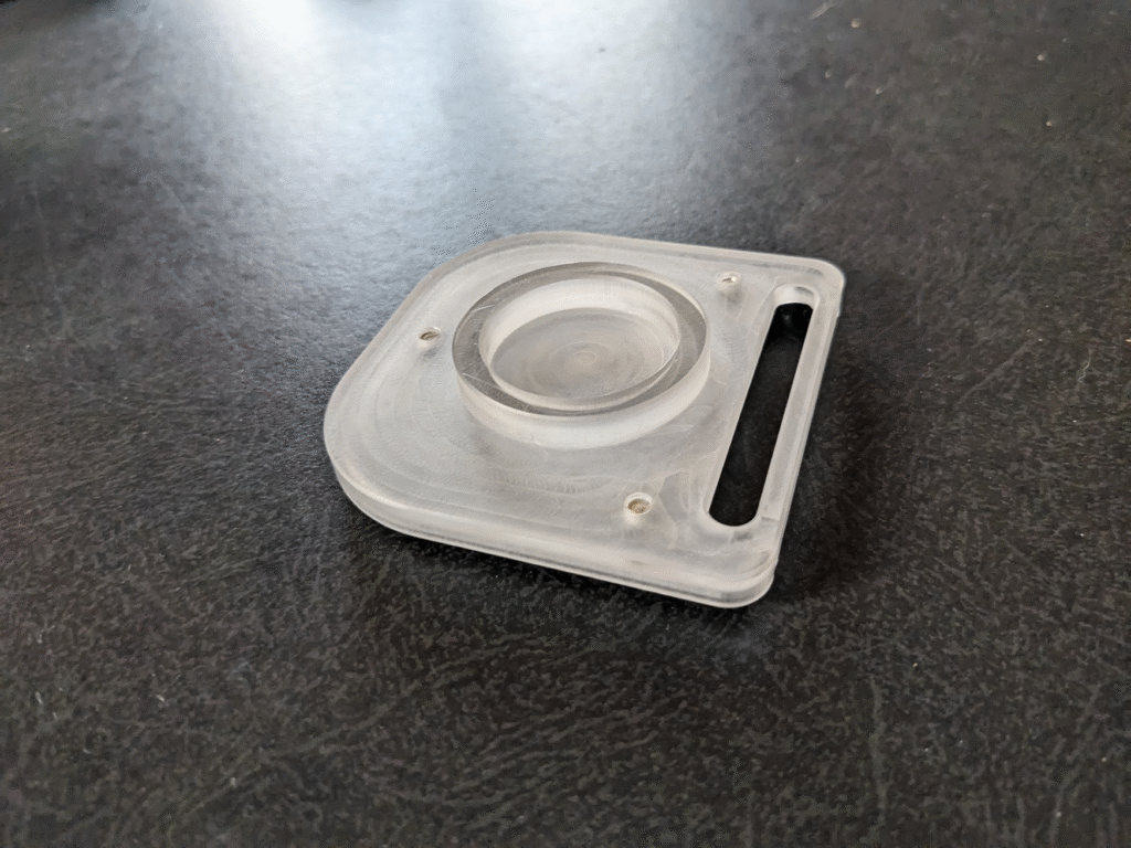
After taking both parts off of their respective machines, making some finishing touches, and assembling them, I had two big takeaways. One was that the rock-stop was really small compared to an off-the-shelf version, and the other that some of its dimensions were somewhat far off from what they were supposed to be as shown by the drawing below. I tried using it with my cello, and learned that it needed to be considerably larger to have enough friction to stay in place but that I had the right dimensions for the endpin pocket.
Version 2
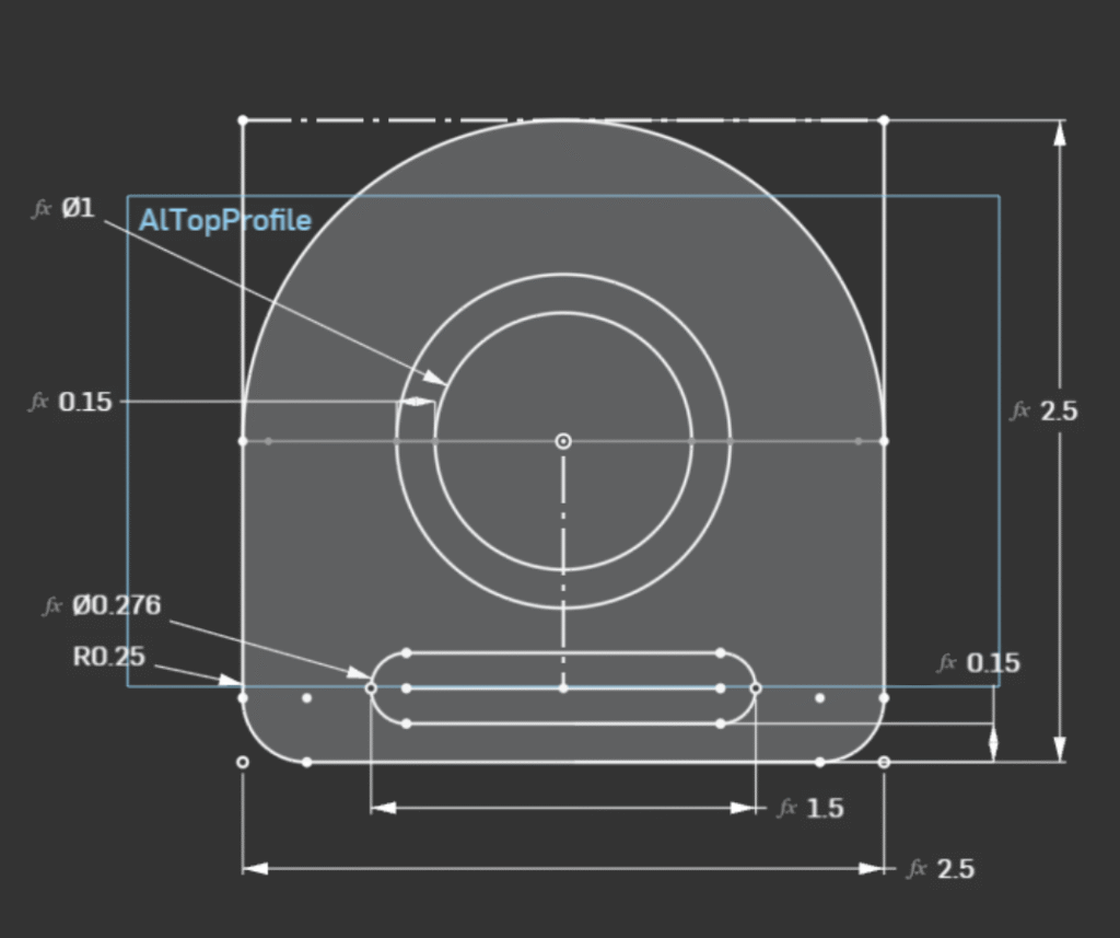
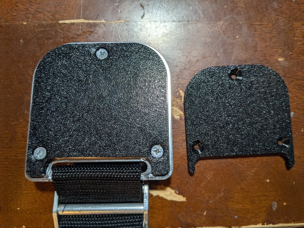
With variable-driven sketches, some quick changes to relevant values (plus tweaks to what I’d overlooked) let me make a second version. The main differences between prototypes are a larger footprint for more friction and a large diameter pocket in the middle. Otherwise, they are pretty much the same.
To keep track of how well changes I made to my machining process worked towards getting better tolerances, I made a drawing of the body marked up with the spec’d dimensions as per my model. As I machined features of the part, I took measurements and either put an orange circle or a slash through important dimensions I called out to indicate if I did or didn’t meet my goal of being within .005″. The results, which I am pretty proud of, are below.
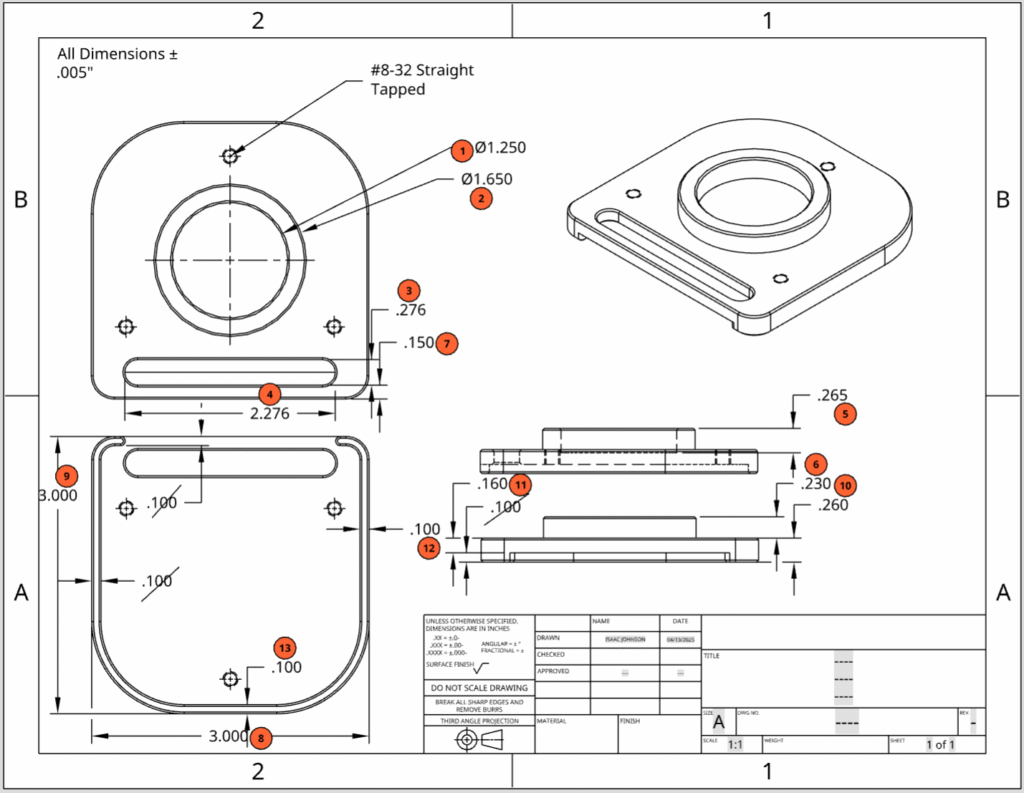
To be that accurate during machining, I tried out some new strategies while keeping the same process as before. Some of these were in how I setup the machine, like taking way greater care in setting my z-axis zero or programming in a couple more finishing passes. Others were more fixture related, like in a vise using the shank of a tool as a hard-stop or hitting the partially secured part flat with a mallet (don’t worry, I saw it online). I try to experiment and improve my methods when I work on personal projects, and producing a sloppy prototype initially gave me a good reason to do so.
This prototype turned out pretty well after machining it, and I was able to use it as a platform for testing different prototypes for strap adjusters and friction pads.
Ideation and Prototyping – Friction Pad
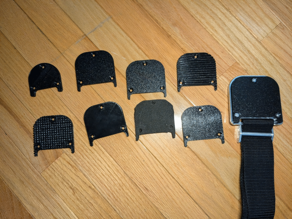
For the first plastic prototype I made a TPU pad that had very little surface area and also didn’t compress much. After I finished the machining the body of the second prototype, I ended up making 7 different pads to try stop the rock-stop from slipping. Each prototype for the pad had one to a few variables changed, and I tested them with my cello against my off-the-shelf rock-stop to judge how well they worked.
Each prototype kept the profile of the body, and I stuck to using 95 durometer TPU to keep iteration easy. I’ve categorized the pads according to similarity, but if you’re curious about their chronological order I have a list1 in the footnote.
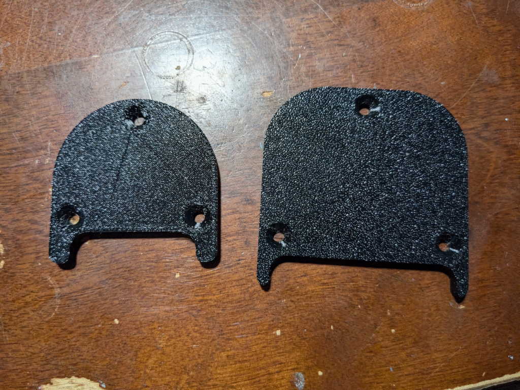
Scaled
The first thing I tested was scaling up the original pad, keeping the same infill and wall loops. It didn’t work too well; the pad was too stiff and couldn’t really compress, leaving it to just slide around. I’ve compared the rest of the prototypes to this one, as its simplicity serves as a good baseline.
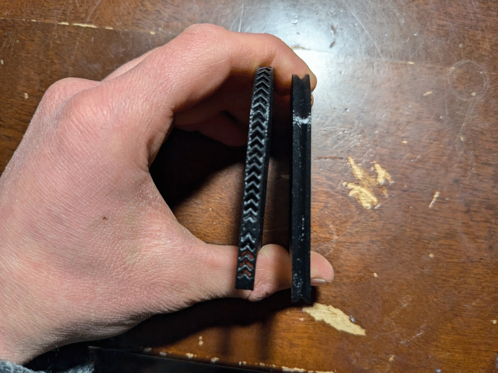
Patterned Sides
The thought with these pads was that the geometry on the sides would fold in and compress more than the scaled up pad could. This didn’t work, namely due to the hard durometer of the TPU and more internal material being stiffer in actuality.
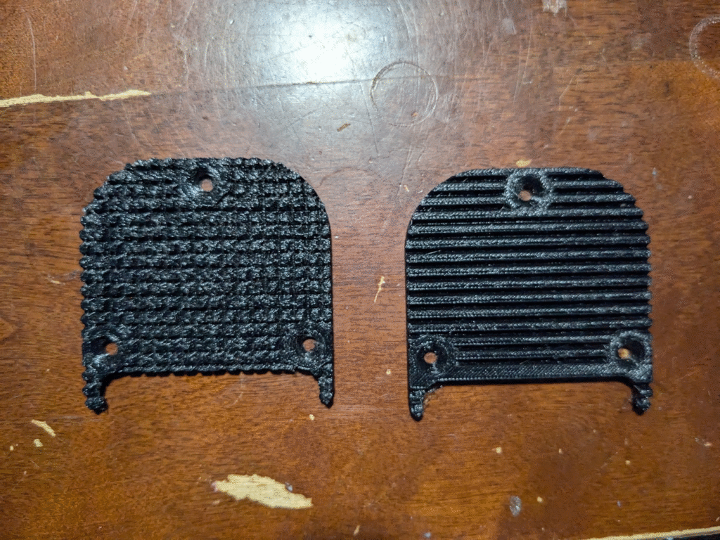
Patterned Bottoms
I hoped that the ridges and spikes on these pads would be able to bend and provide a spring force, but like the previous prototypes we undone by the hardness of the TPU. These actually worked worse than the others, having less friction from less material contacting the floor and less internal material to compress.
Different Density
All the other pads had tweaks to their external geometry, but for these I tried changing their internal structure. I tried using a piece of foam I had lying around instead of TPU, but it produced way less friction. The other worked way better; I had change the type of infill in the slicer from an omnidirectional pattern to a more directional one and oriented the part to make the infill be perpendicular to the force that the endpin would exert. With a bit less infill density and wall thickness, this pad worked pretty damn well.
Final Friction Pad
Taking what I had learned from my testing, I scaled up the body piece of the rock-stop and printed the larger friction pad with a low infill percentage, only 2 walls, and infill perpendicular to the endpin’s force. I expected more testing, but the pad was pretty comparable to the rock-stop I used for reference.
Ideation and Prototyping – Strap Adjuster/Buckle
The last part that I needed to prototype before I could continue was an adjuster for the strap. Different people prefer different lengths of strap to hold their cello at a comfortable angle, so this is an important part of the rock-stop to get working right. To figure out how to make a functional buckle that could be used for adjustment I made a series of 3D-printed prototypes.
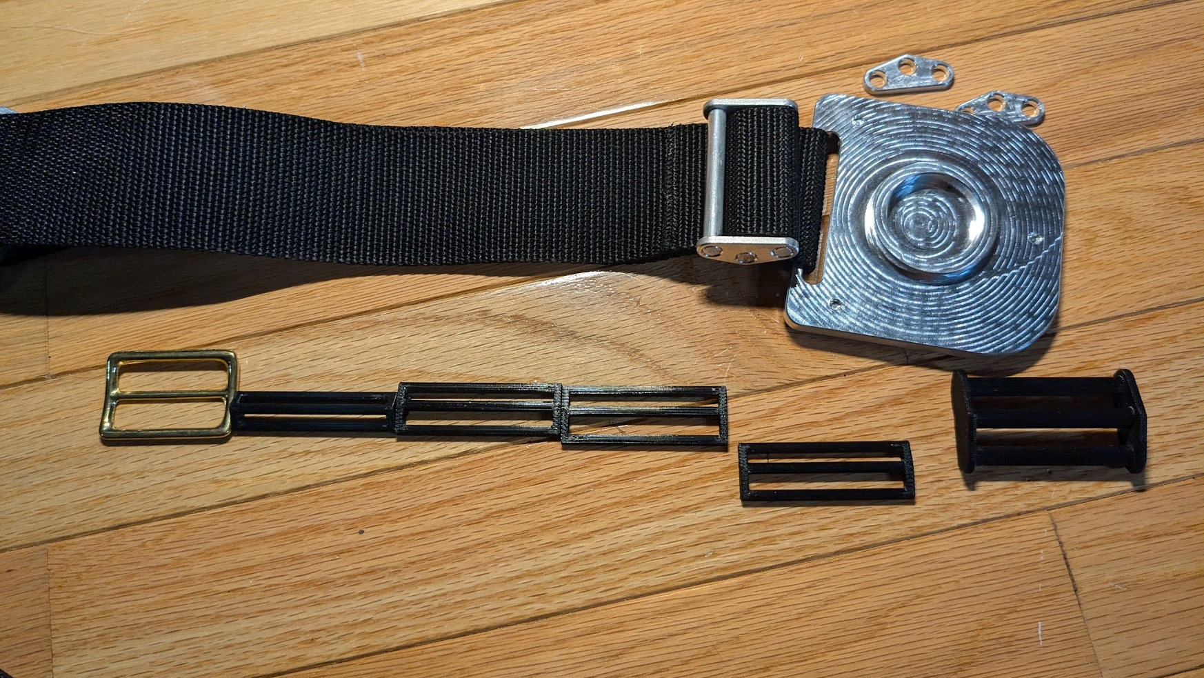
As a starting point, I bought a buckle from a local surplus store and learned how it worked with a helpful video I found. This helped me determine what variables to prototype, and consequently how to draw another variable-driven sketch. With a bit of trial-and-error, I landed on a good between some aluminum dowel rods I found to tension the strap. The final plastic prototype I made had the same geometry I planned to have for the actual aluminum buckle, letting me verify that it’d work before using up a more costly resource.
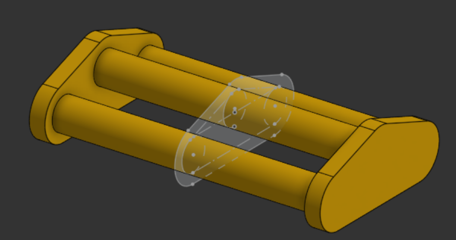
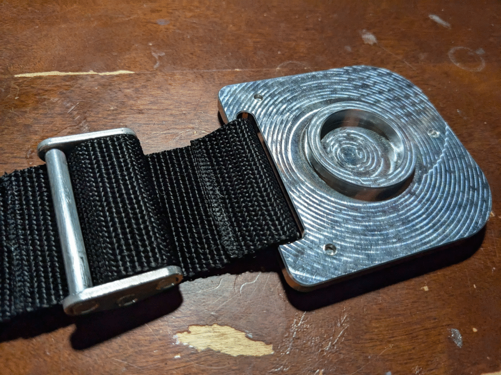
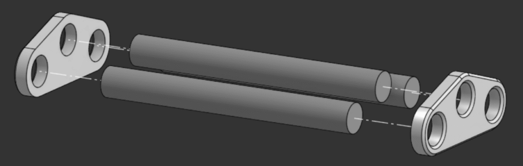
After confirming that the last plastic prototype worked, I broke its model into 2D side plates that I could machine and a length of dowel a bit wider than the strap. Knowing a hammer would be involved in assembly, I machined an extra couple side plates and had extra aluminum bar handy after cutting the dowels.
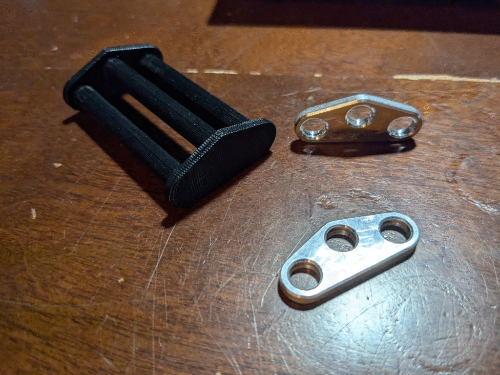
Assembling the buckle after fabricating its components didn’t go as I expected, but not in a bad way. I originally intended to hammer the dowels into the plates then braze where they met, but my press-fit tolerance was too tight for the dowels to go in straight. What I ended up doing was getting all of the dowels started into one plate crooked with the hammer, forcing them partially into the other, then pulling everything together in a vise. This worked beautifully (although it scratched up my shiny parts), and with how tight the holes of the plate were I didn’t need to braze anything.
Final Manufacturing and Assembly
With a working buckle and friction pad, plus what I’d learned from the body prototypes, I felt confident about making a final, aluminum version of the body. There was one last part that I needed to make beforehand.
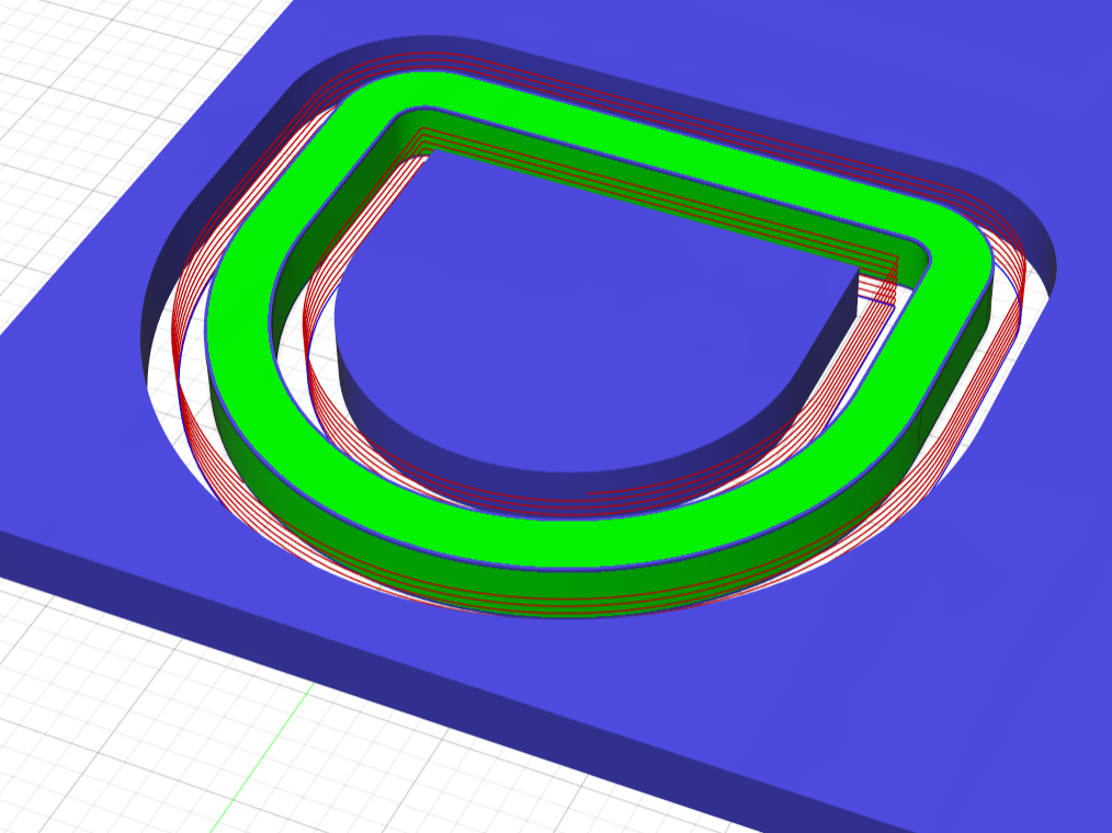
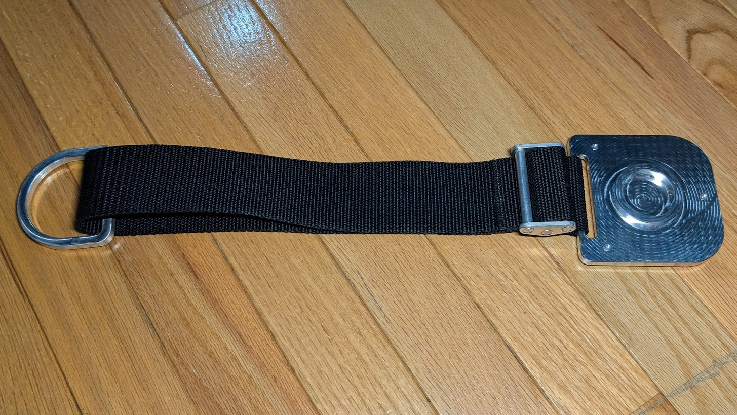
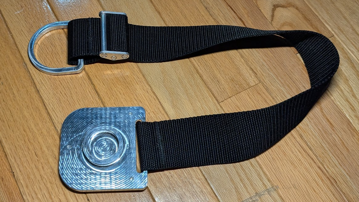
I needed a way to connect the strap of the rock-stop to a chair, for which I made a simple D-ring. Using tape and super-glue, I secured a sheet of 1/4″ aluminum to my wasteboard and ran some ramping passes on the inside and outside profile. This fixturing method made dealing with the part and leftover stock simple, but with a slight offset on my z-zero left some adhesive from the tape stuck on the part. To get that off and make the ring look a bit nicer, I took a wire-wheel to it.
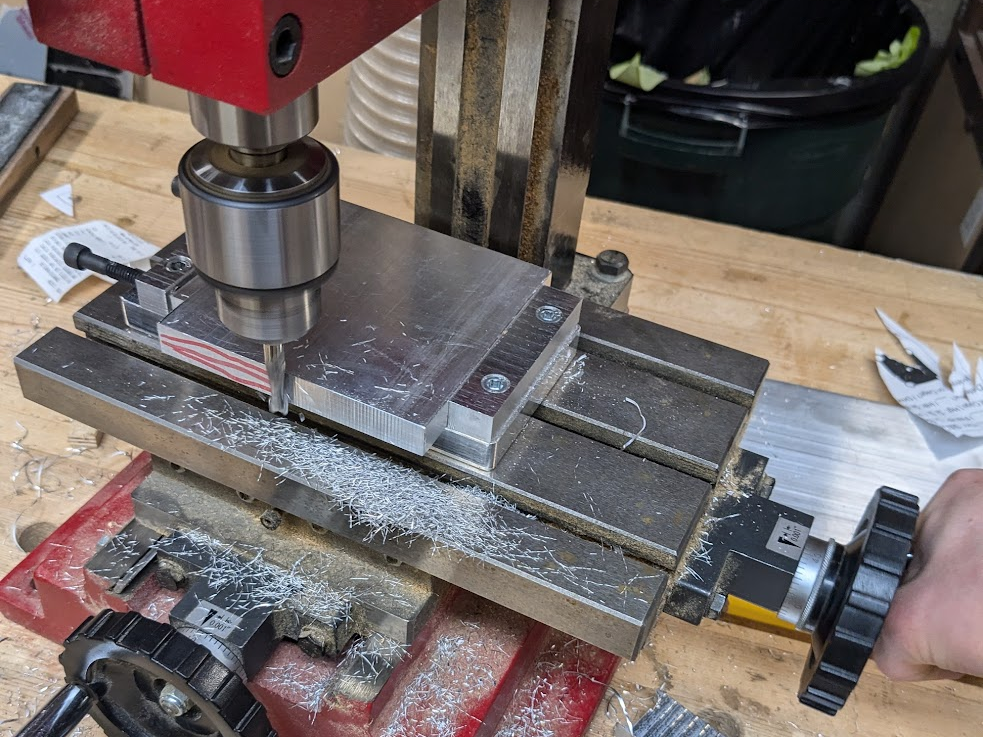
Machining the body the rock-stop wasn’t as simple. For the challenge and to hold it more rigidly, I planned to use a vise for both sides as I machined it as opposed to starting on the wasteboard. This had the added benefits of more aggressive toolpaths and more options for the order of programs, but meant more prep-work. I didn’t have a good small enough piece of 1/2″ aluminum to fit in my machine vise, so I cut down a slightly larger piece and squared it up in on an old mini-mill. After some initial hiccups and half-disassembling the mill, I had a chunk of aluminum ready for the CNC.
I started with machining the bottom pocket and outer profile, as I didn’t want to risk scratching up the top face of the rock-stop with my vise’s parallels. To get a really clean finish of the edges of the part, I tried using a 3-flute endmill instead of the O-flute or 2-flute tools I normally use. Even with yet-to-be-optimized tool data, it left a better surface finish than I’ve ever gotten; better even than that of the 4-flute chamfer endmill I used to finish off the bottom.
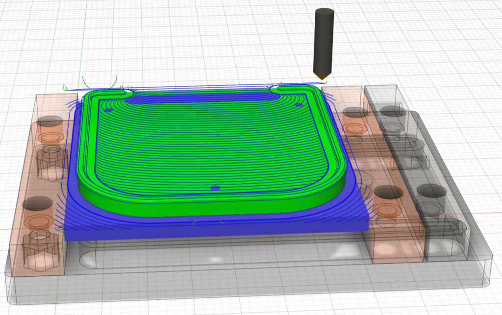
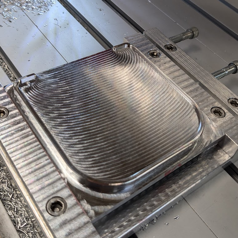
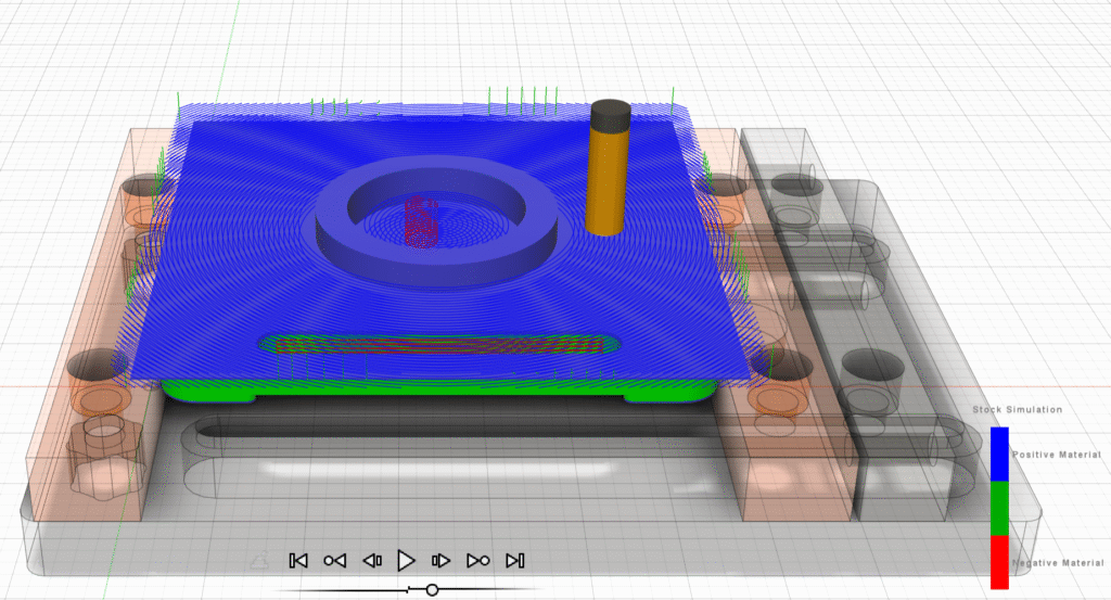
My next set of operations were meant to finish off the part by machining every feature visible on the top face, but I ran into a problem. The toolpaths I started with used an O-flute to rough out everything pretty aggressively: too aggressively. With each pass the endmill pulled the part slightly out of the vise up until I noticed, at which point it was ripped fully out of the vise as I hit the computer’s stop button. These passes dug too deep for the body to be fully recoverable, so after walking away for a bit I came back to salvage what little I could from the crash. This meant rerunning the operation that led to the issue with some toning-down, starting with a lessened stepover (that still ripped the piece out) and then a halved depth of cut that worked just fine. To add insult to injury, I forgot to re-zero the second time I put the piece back in the vise and the features were shifted forward; I still ran the rest of my operations–minus some vanity chamfers–to see if anything else caused issues, which let me know that my 3-flute finishing passes and 1/8″ bores worked perfectly fine. With nothing better to do, I started over with another piece of 1/2″ stock I had on hand.
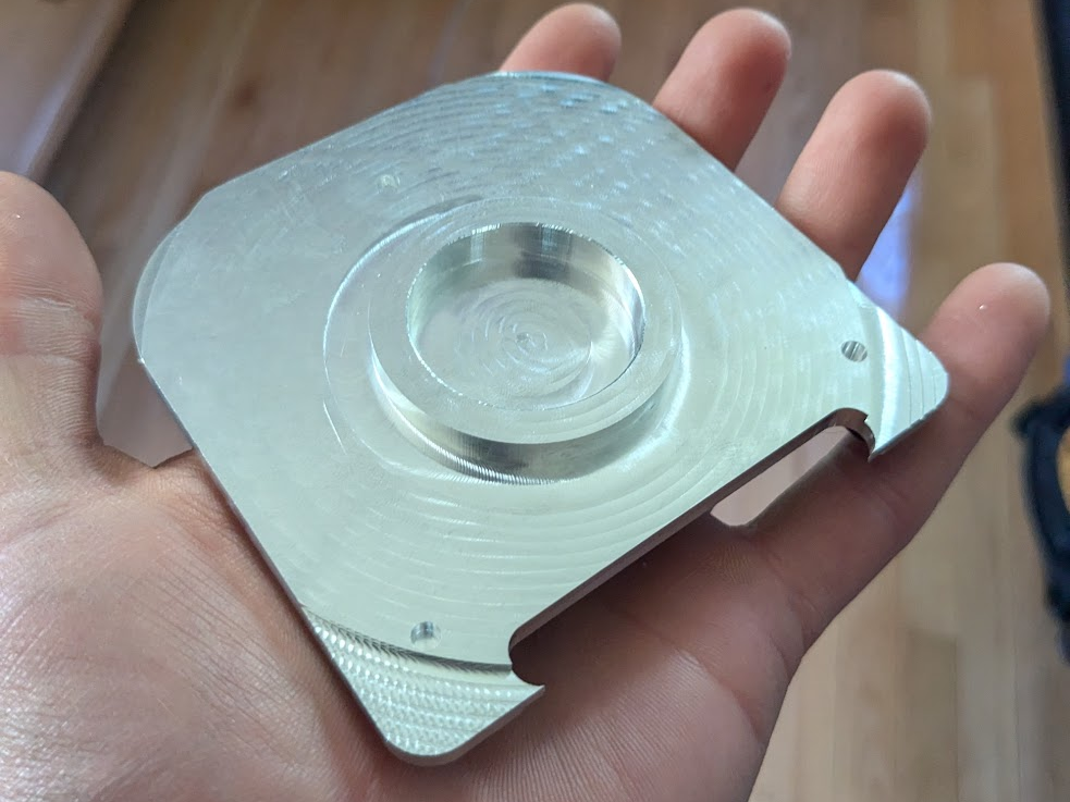
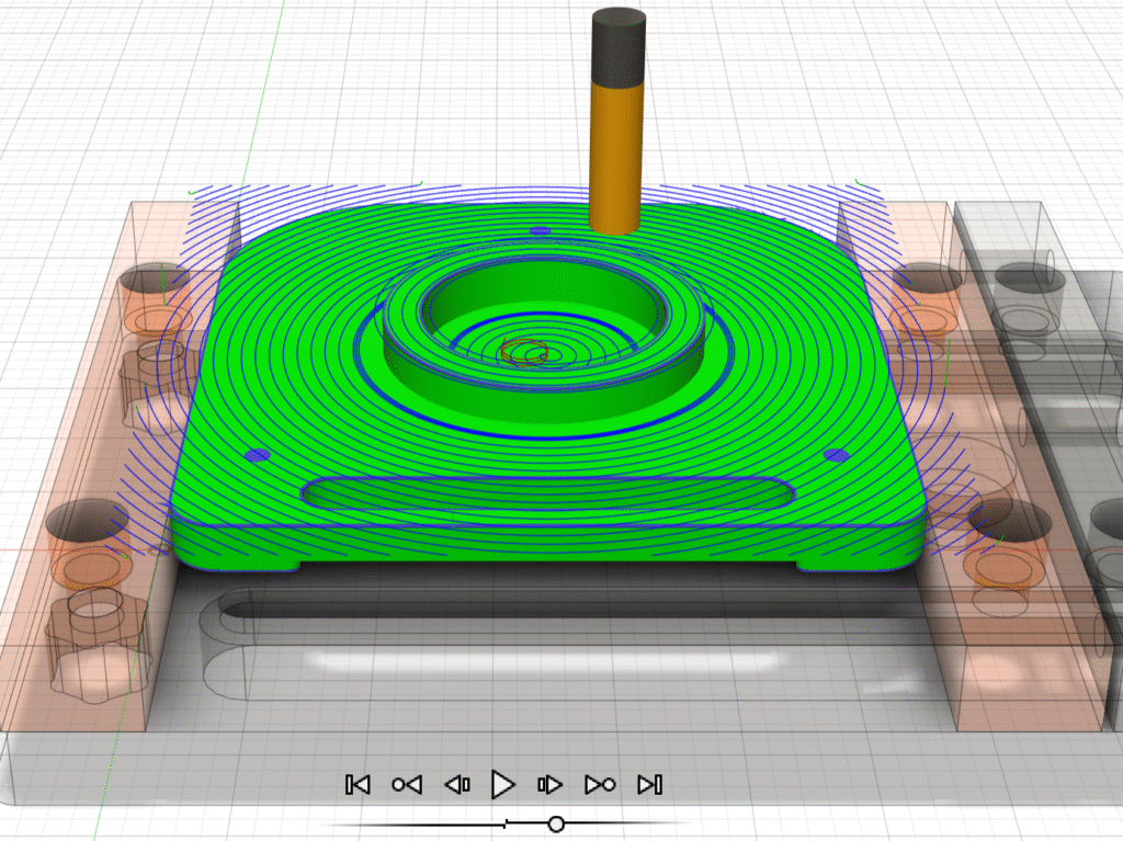
Cutting and trimming the stock down was faster with some practice on the mini-mill, and machining the bottom took no time at all since I could re-use all of those toolpaths. Before long I was back machining the top, roughing it with the O-flute with small, .1″ deep stepovers without any issue thanks to using the messed-up body as a guinea pig. Finishing passes to remove intentionally left over material, a couple bores, and a nice chamfer on every surface left the part ready for some manual finishing touches; a couple spots deburred and #8-32 tapped holes left irt complete.
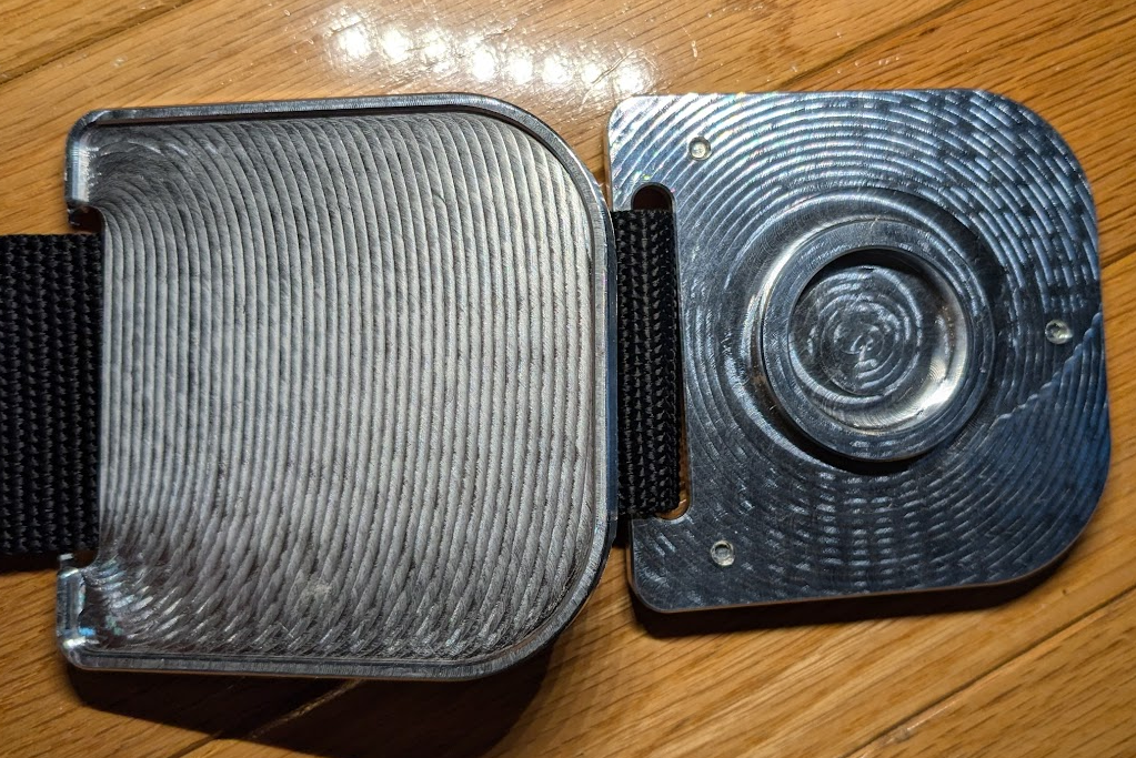
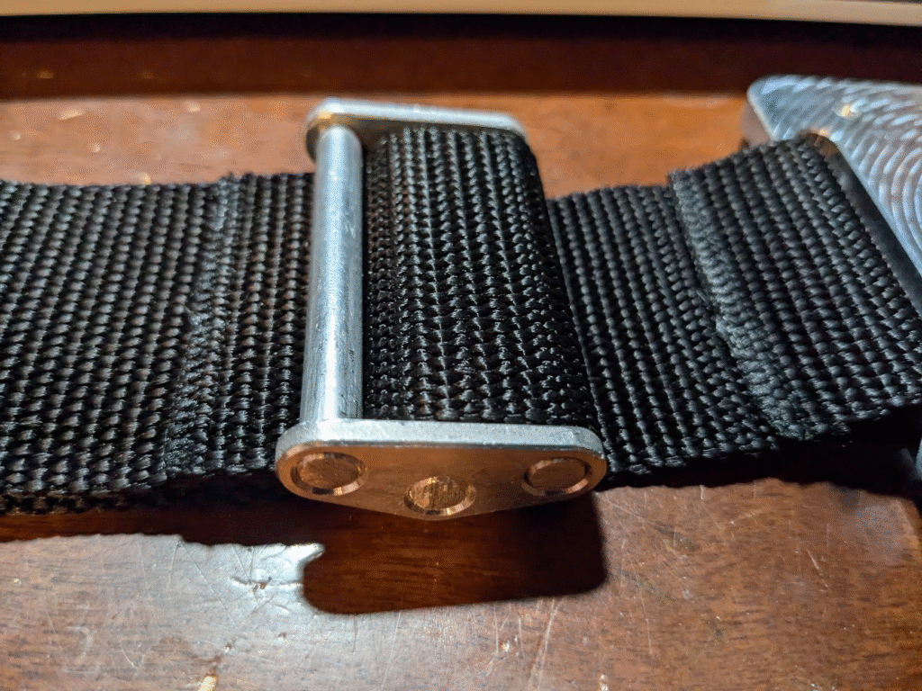
The last step before I was done with the project was to assemble everything and sew the strap in a few key places. I fed the strap through the D-ring, buckle, and body then cut it to length based on what looked right at its shortest. After sewing it at both ends to keep everything connected, I realized that I didn’t like how ridiculously long it was. So, I cut and trimmed the end where it connected to the body, sewed it together, and didn’t like it again. The third time, I fully extended it to what i wanted the maximum length to be, trimmed it, and sewed it together yet again. This left the distance between the end of the ring and the endpin pocket at a maximum of 26″ and a minimum of 15.5,” which I feel is a very practical range.
Takeaways
I’ve learned a good amount through this project, and my teacher loved the roc-stop when I gifted it to her. My key takeaways have namely been specific techniques for better using the machine vises I’ve made, improving machining tolerance, and ways to integrate fabric into designs. I’ve also learned the basics of how to operate and maintain manual mills, something I’ve wanted to do since I first started using CNC routers.
This project has also been a good opportunity to practice skills such as making clean, modifiable sketches in CAD and systematically prototyping.
Link to CAD Document – Custom Rockstop
- Chronological order of what friction pad designs I tried:
Small > Scaled up > Side groove > Ridged > Spiked > The one with the arrow pattern > Foam > Low density > Failed print of scaled up low density (not shown) > Final/Successful print of scaled up low density (attached to rock-stop) ↩︎