
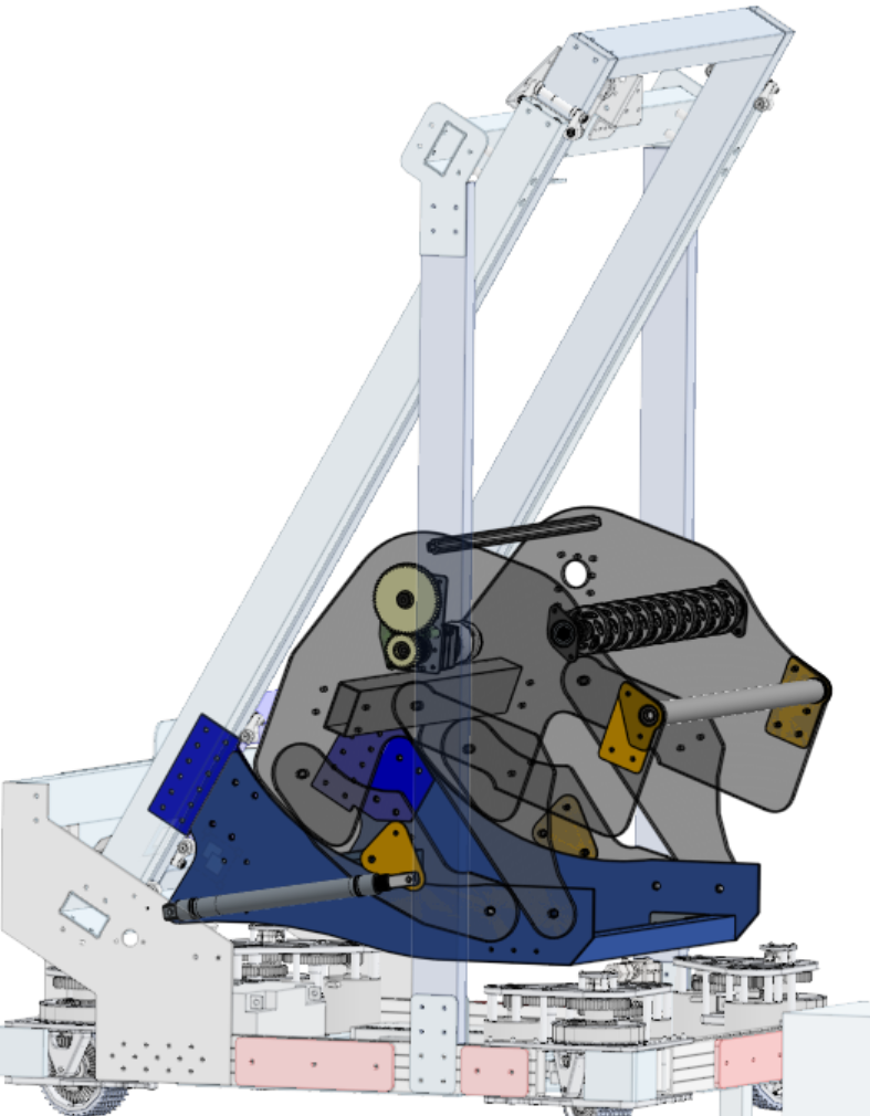
Why – For the FRC robotics team I am on, we have a new game every year that we design a robot for. In 2023, I was tasked with creating an arm to grab and score two objects, which had to grab from the floor and an angled chute then score onto high up goals.
Key Parameters – Fit within preexisting frame and mount to preexisting elevator mechanism, able to lower to the floor, at correct angle when stowed to grab from angled chute, able to be manufactured on a CNC router.
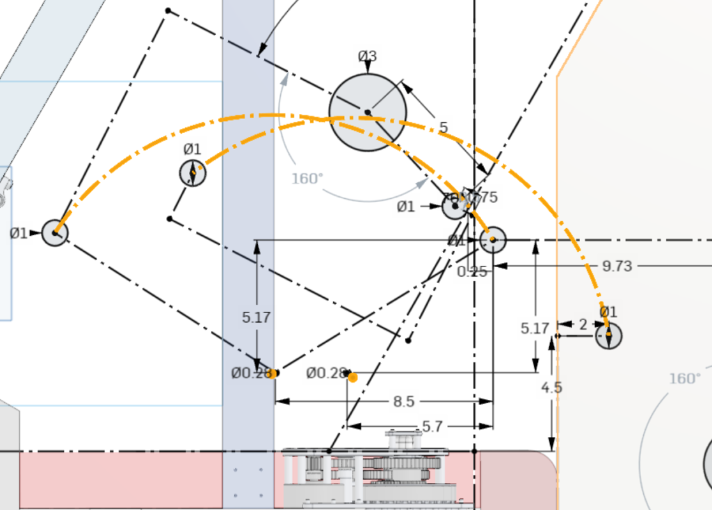
Process for the complicated bit – Draw out key parts of surrounding situation, like the location to mount to, angle and travel of object from chute, area mechanism must fit within. The necessary locations for wheels was figured out from prototyping, so draw locations and angles that holding wheels need to reach, and constrain pivot locations. Mess with locations of pivots until the arms won’t interfere with each other. After the arms and mounting plate are drawn and extruded, create two circles with the radius the length of a piston and clevis fully retracted and fully extended. Draw two circles that center on the outside of one of the two circles, then put them in the same location relative to the extended and retracted arm to create a mounting point, then draw an arc centering on the pivot point of the arm to depict the motion of the piston head as it retracts. Use that setup to determine the mounting point of the piston that actuates the mechanism and fits within the area dedicated to the mechanism.
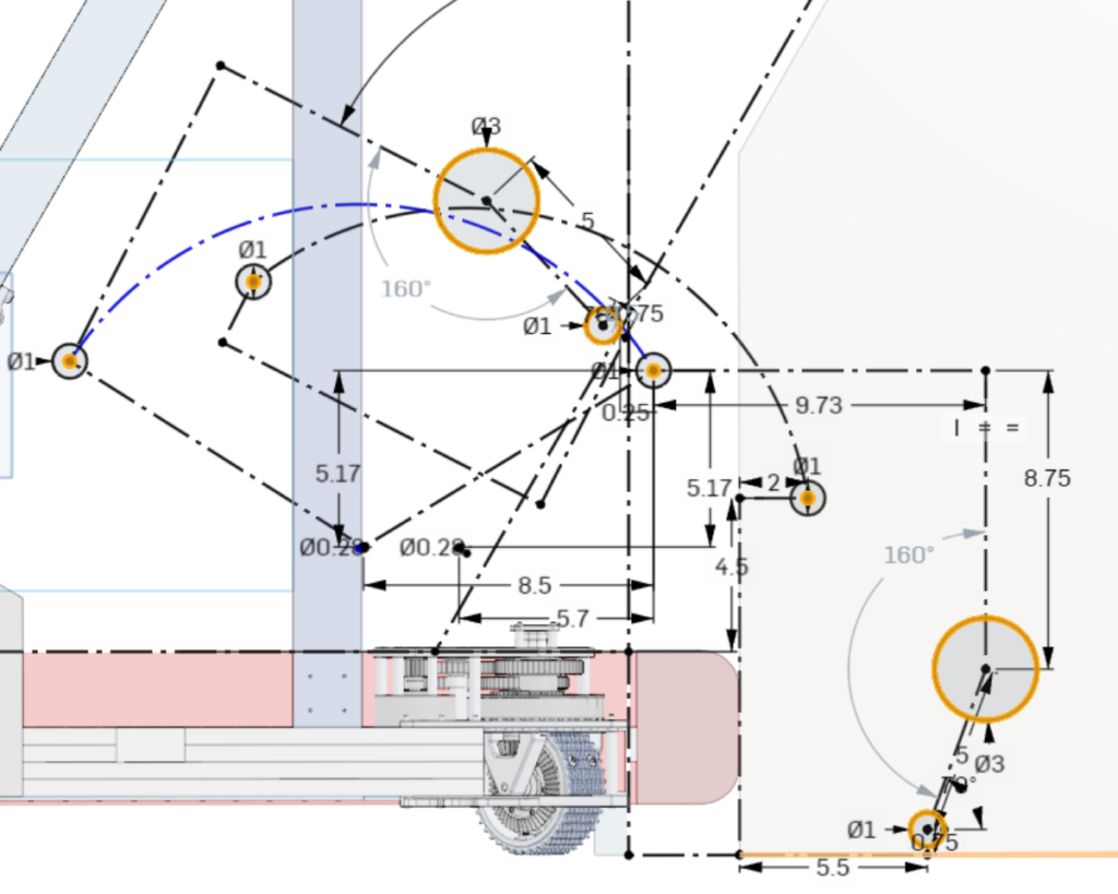
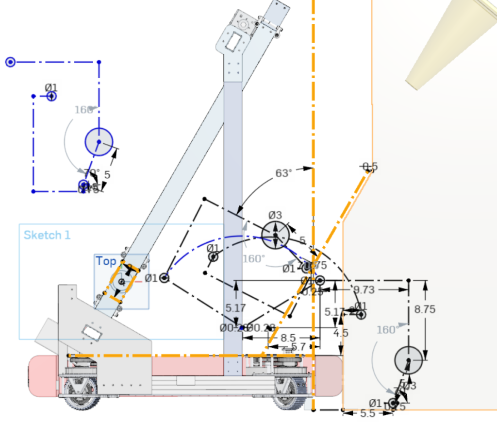
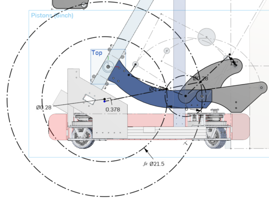
Process for the less complicated bit – Use the pivot locations to create arms, adding a hard stop to limit their movement if anything breaks in action. On the arm that is driven by the piston, add an Aluminum plate that reinforces the point where the plastic arm is pushed from. Also create a mount that can be removed from a plate attached to the elevator with only a few bolts if the entire mechanism needs to be replaced. Draw and extrude the shape of the intake plate, then draw the gearing and belting that transmits rotation from a motor located near the pivots to reduce the torque needed to actuate the arms to the holding wheels’ location.
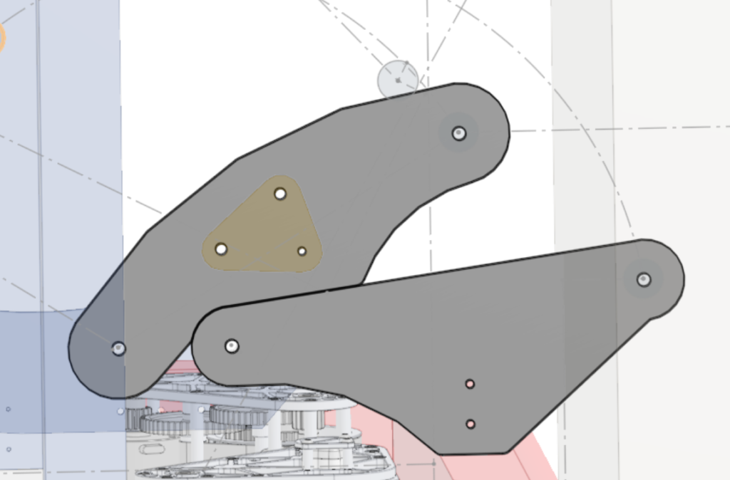

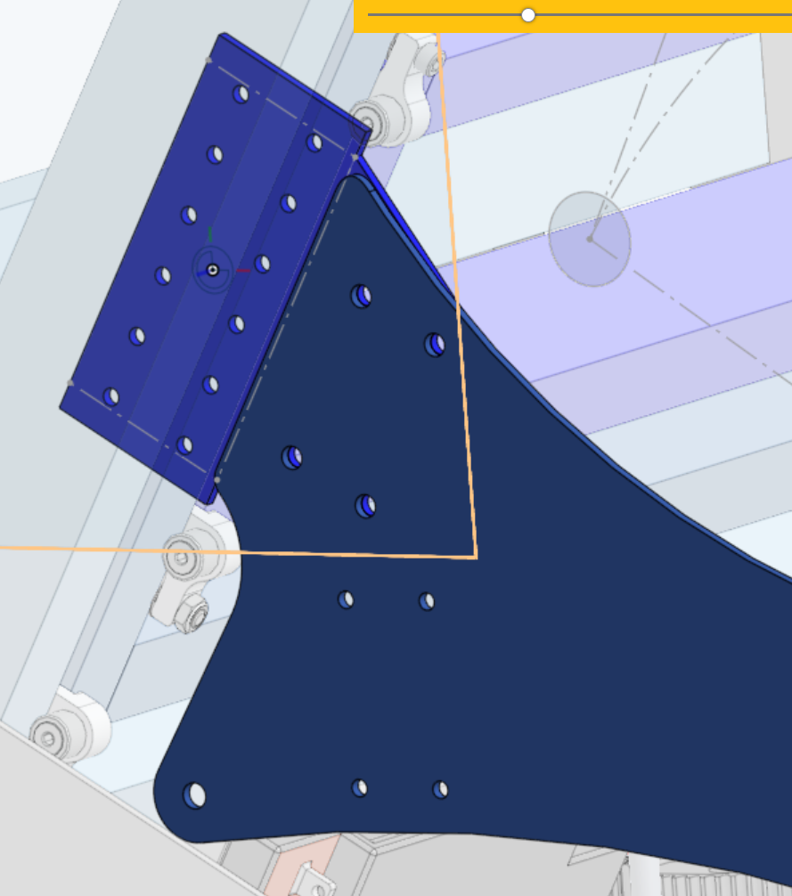
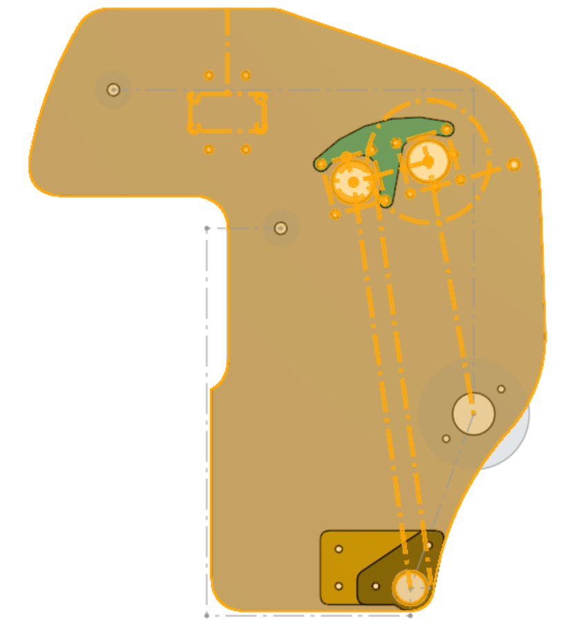
Manufacture and Assembly – The arms and intake plate were designed to be cut out of 1/4″ Polycarbonate, which was selected for its strength and ability to flex and not bend when hit. The mounting plate and attachment point on the elevator were designed to be cut for 1/8″ Aluminum to be rigid and had very little chance to be bent, especially with box extrusion as bracing. Non-structural plates, the arm brace and unmentioned bearing retention plates, were machined out of 1/16″ Aluminum due to the little strength required of them. The mechanism used 2″x1″ and 1″x1″ extrusion along with some hexagonal shaft for connecting two sides, attached using L-channel extrusion and some gussets.
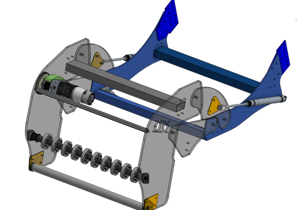
Issues and what was learned/changed – A major issue with the arm was its weight, making it slow to retract. One early fix that we went with and stayed with was adding pneumatic shocks that were positioned to push upwards when extended, which allowed the arm to be viable. Another fix that was tried but not implemented permanently was swapping out the 3/4″ bore pistons with 1″ bore pistons, which hastened retracting the arm but used up more air than the onboard compressor could keep up with. Another issue was with running out of compressed air, which was lessened with the later addition of another air tank and also by relying more heavily on maintaining the stored position and relying on the chute to collect objects, the only extension being to score and only rarely collecting from the ground. An issue in the design process was the cluttered sketch that determined geometry, which made it complicated and annoying to change parameters or pivot locations. This has led me to use different sketches for drawing limits, movement, and other important details.
Link to CAD document in Onshape – Cicada 2023