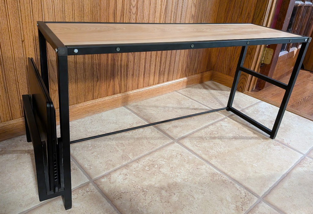
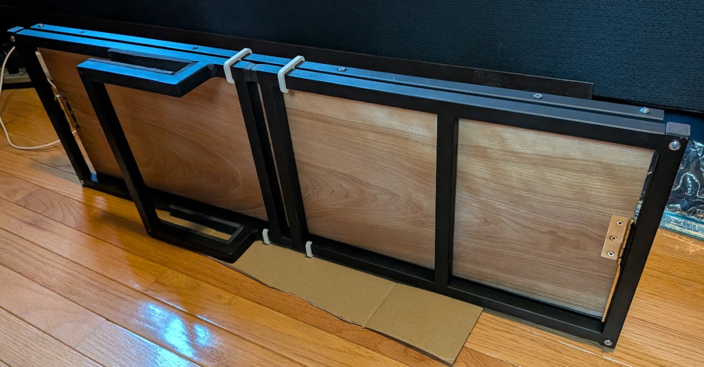
This project has dragged on for most of the summer due to my time being split between interning full-time at Medtronic and socializing, but that’s not a bad thing. It’s been a fun opportunity to relax over the weekends and try new techniques in fabrication, plus I’ll put it to good use at college.
Requirements
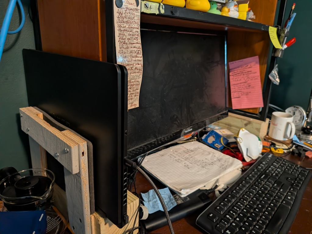
I’m bringing this shelf to Madison and want to minimize the hassle of moving, so the thing needs to collapse for easy transport and for convenience it needs to stay in one piece even when taken apart. Additionally, I like my shelf at home where I can fit my monitor under it, hang hooks and stuff from it, and stow my laptop out of the way in a cubby; I wanted to replicate that with this shelf.

Planning
Normally I start my projects in CAD or with paper drawings that lead to CAD, but this project really doesn’t need a full CAD model. So, I stayed in a notebook and only modeled the tubing inserts I planned on machining and accessories that needed to be 3D-printed.
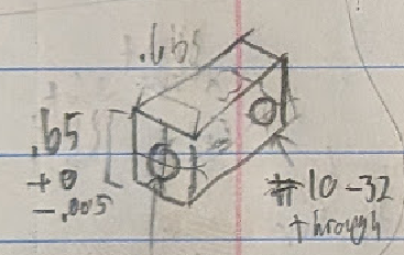
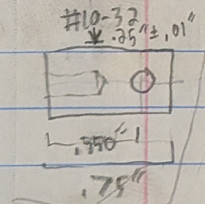
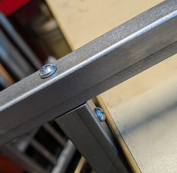
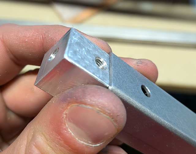
My plan was for the shelf to break up into 3 parts: a long flat shelf panel, a basic leg panel, and a leg panel with a handle/cradle for my laptop. The whole thing was to be 3/4″ square steel tubing so I could weld it together easily while keeping it light, plus so it could be hollow to shove parts into. One of these parts is a machined aluminum insert that would bolt to the inside of the shelf panel and allow me to bolt the leg panels on at the tube end.
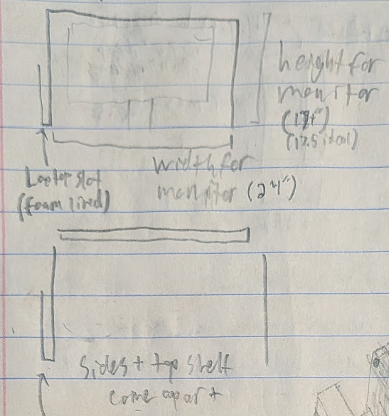
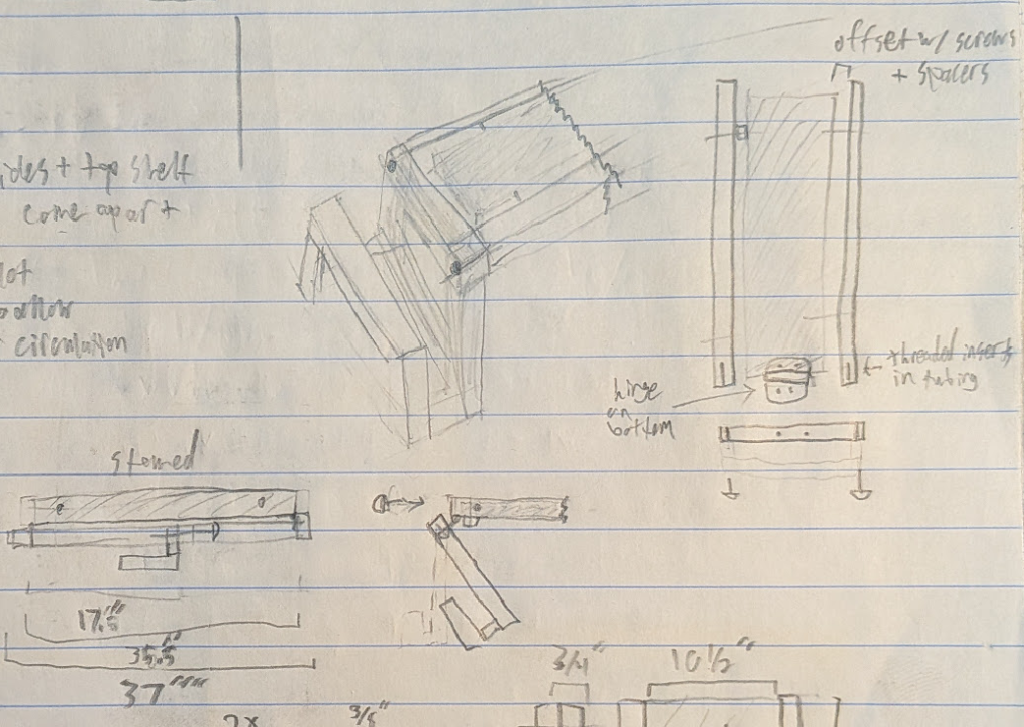
To be able to use the shelf panel as a shelf, I planned on sandwiching a 35.5″ wood plank between two 35.5″ tubes that interfaced with the leg panels. The plank would have a hinge screwed onto the bottom face of both sides that attaches the the leg panels, allowing them to fold up. The length of the plank is determined by the height of both the leg panels plus some tolerance for foot-inserts to prevent scratching up my desk, and the leg height is in turn set by the height of my monitor at ~17.5″.
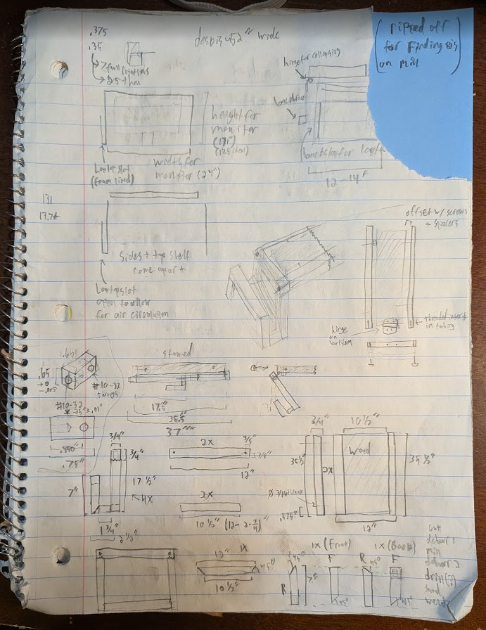
Moving on from the general idea, I drew out the legs with the tube orientation and lengths I needed so I could determine how much steel I needed. I planned on having a horizontal tube go the whole depth of the shelf for interfacing with the shelf panel, which allowed me to have a flush top and both holes I’d bolt through on the same piece of steel. Additionally, I intentionally oriented the tubing that gives the shelf its height to be open on the bottom for in-line foot inserts. The handle didn’t need any openings, so I planned on cutting all those pieces at 45 degrees to make welding it together easier.
Metalworking
After drawing out the plan, I needed 20′ of steel tube. I used a bandsaw to cut it to length, but the blade doesn’t come down straight and couldn’t be adjusted to fix that. So, I added extra length to be milled off on a micro mill and later used it to accurately position bolt-holes. Another benefit of the mill was that flat, squared tubing would make welding setups much easier. To get nice 45 degree faces on the handle segments, I cut them at an angle on the bandsaw and pivoted my CNC router vise about one of its mounting bolts using a speed square and a clamp to prevent it from rotating. This won’t be perfect, but it’s the best I could do with the tools I have available.
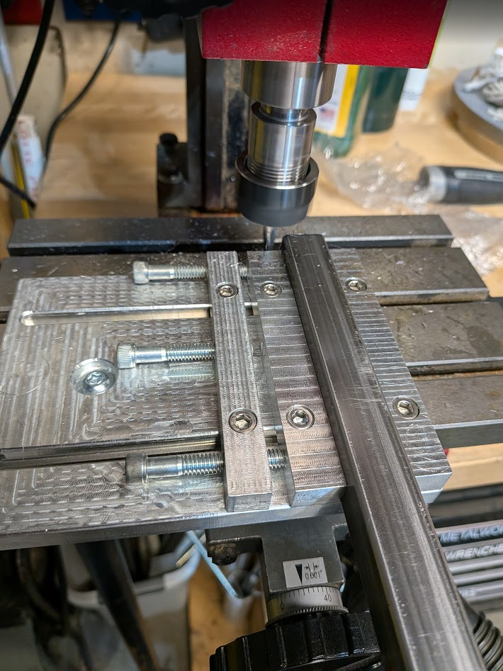
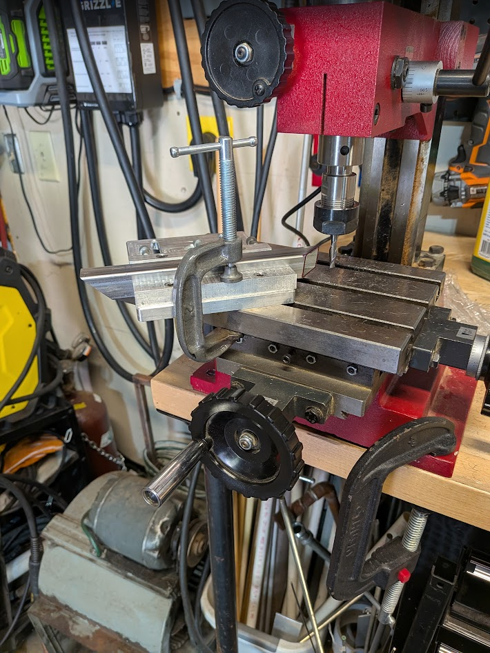
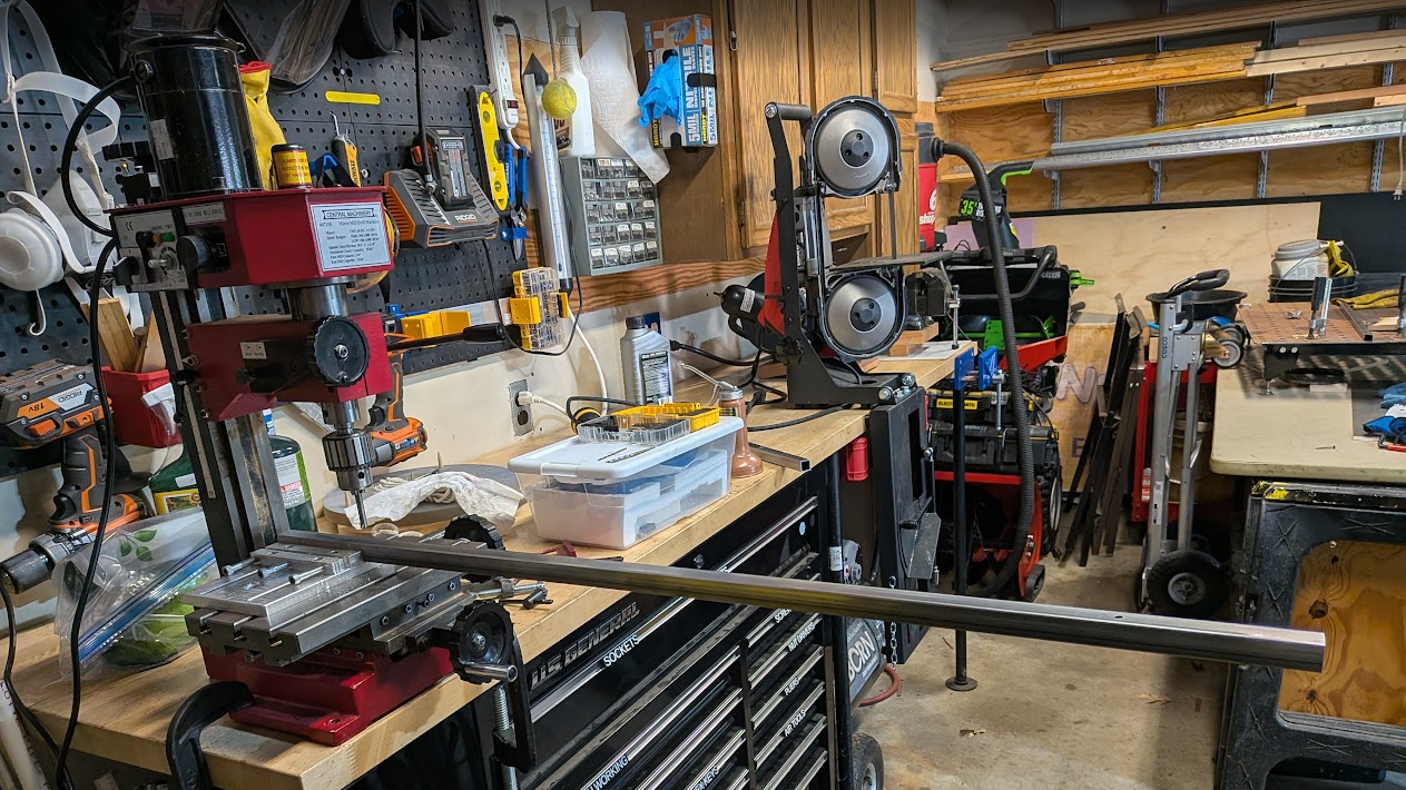
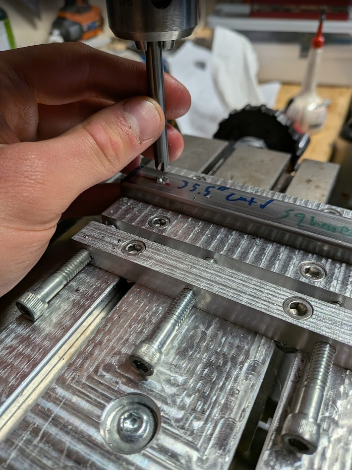
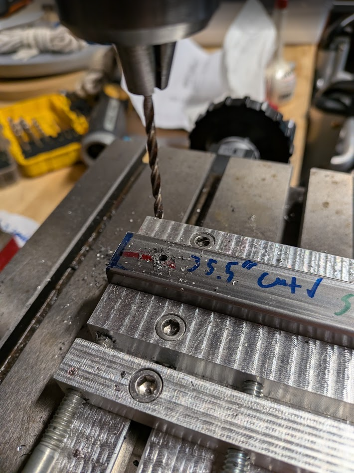
I used the mill to drill holes, offsetting the spindle half a tube width from the static jaw and the distance from the end I needed. I also used a speed square to push tubing flush against the end of the jaw, then secured the tube and plunged a carbide chamfer tool to mimic a spot drill. After a pre-drill, drill, and countersink cycle I flipped the tube and repeated for the next hole.
Next was welding prep and the actual welding. I sanded down all of the tubing to remove scale, then I did test-welds on scrap tubing to figure out the right MIG settings. The first welds I ran were tacks to secure some hinges to the top bar of the leg panels, then I tacked the corners of the legs as precisely as I could using a 90-degree vise and careful alignment to keep the tube segments all in one plane and properly butted against each other.
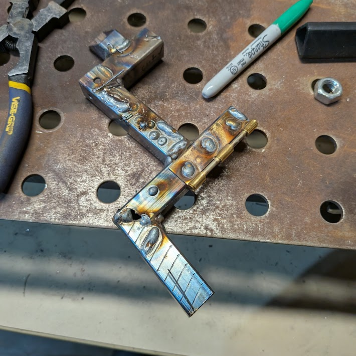
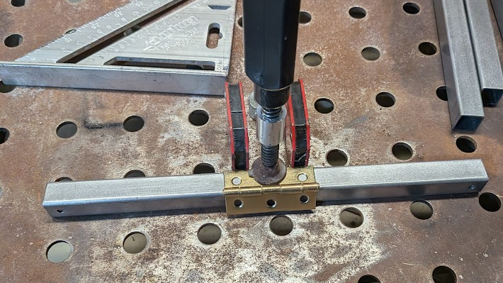
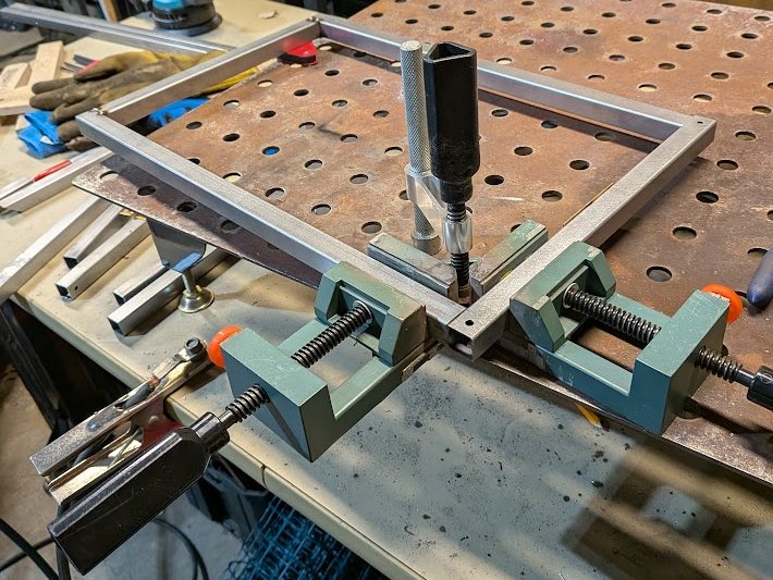
The handle was harder to setup, but using magnetic squares I kept the segments-to-be-welded aligned and only tacked until each segment was secured. Next I lay a bed down all of the flat seams. I avoided welding the interior corners since there was little to no gap due to the faces being machined, but for the exterior corners I ground them down and lay a bead to add material to round the sharp edges with an angle grinder. To finish off the handle, I ground down the rest of the beads flush and hide the welds.
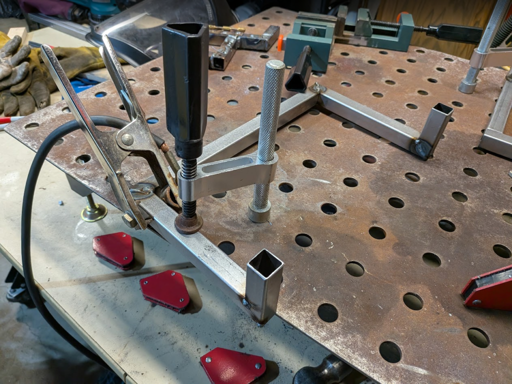
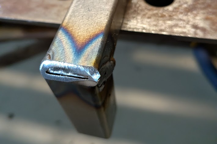
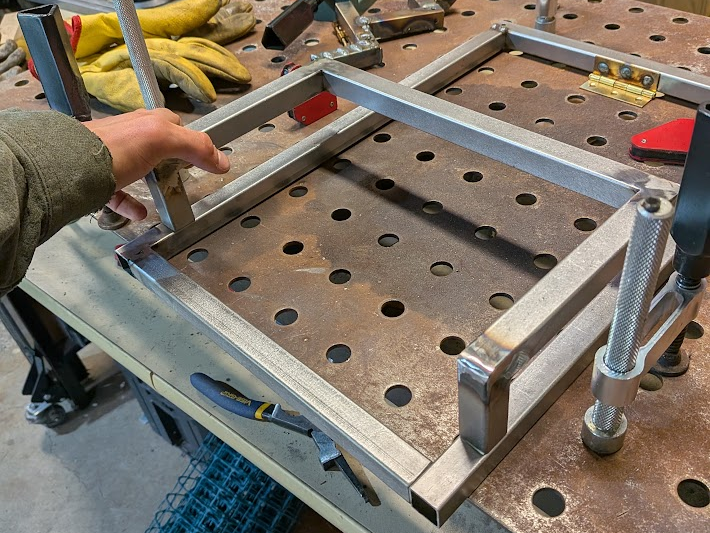
My drawing had the handle positioned at the bottom of the leg, but I moved it upwards to create more vertical room to hang things. In the same vein, I added an additional segment of tubing to the other leg. Finally, I tacked and laid beads to on the handle and again hid the welds with a grinder.
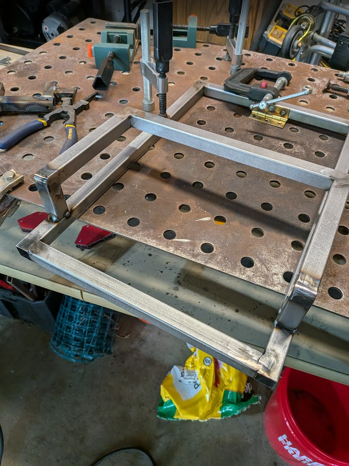
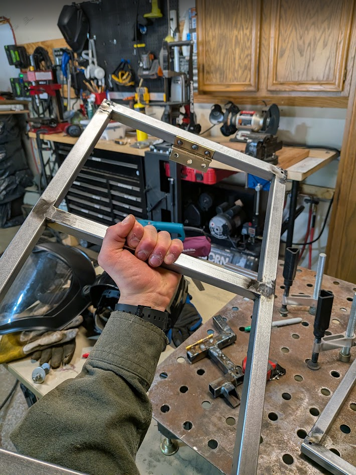
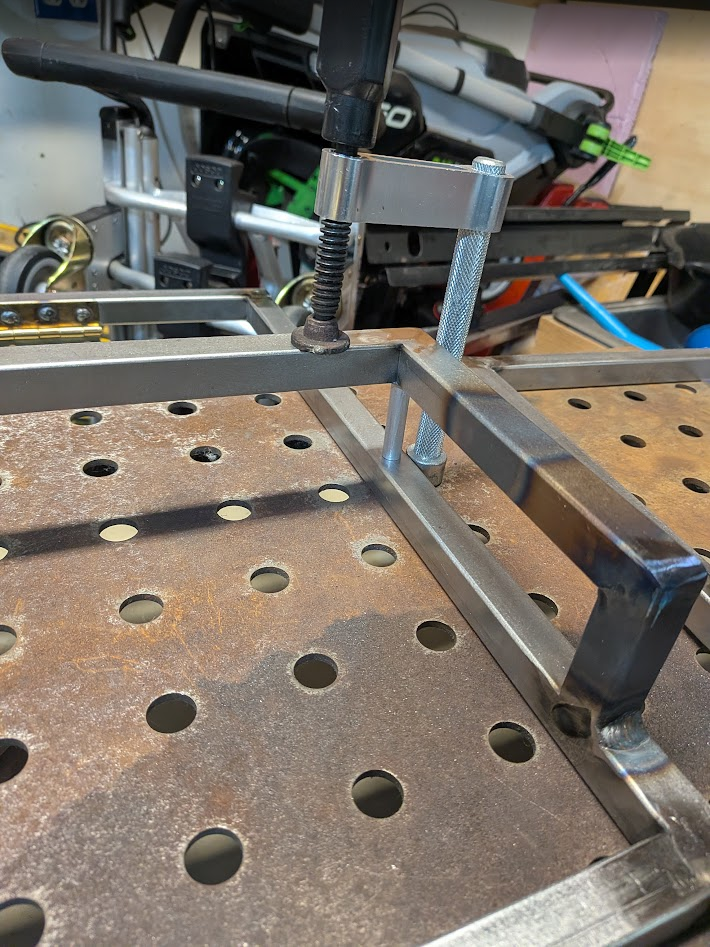
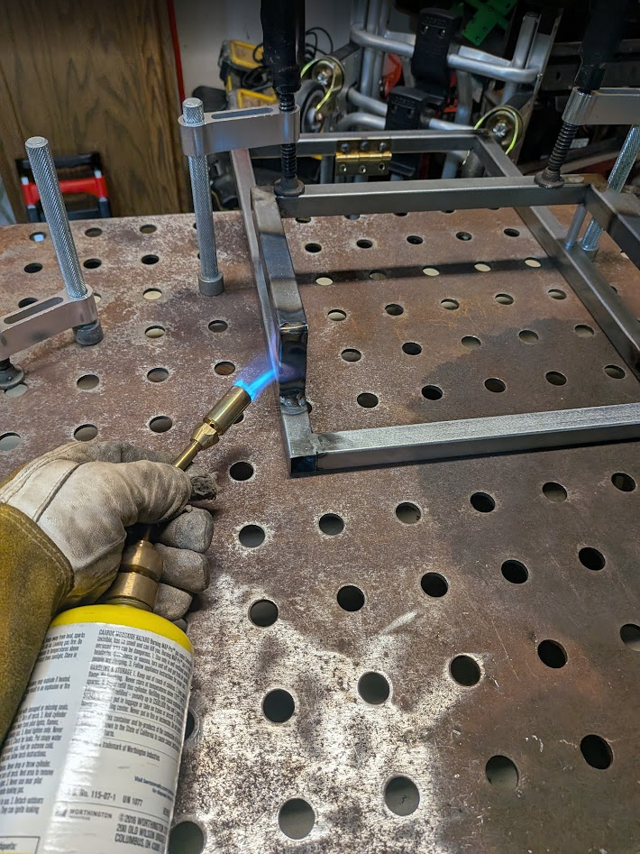
When I attached the handle, I had to force part of it into place with a clamp due to some slight misalignment. The floating section was also a different offset from the leg tubing on either side, so I applied what I learned in my intro to MS&E class to limit strain while deforming the material. I shoved some aluminum rod that wouldn’t mar the metal in b\cut to the right offset between the leg and the handle on both sides, then got the metal red-hot with a blowtorch at the areas of the handle that my Statics class taught would have the highest internal forces. Theoretically this should add energy for the steel’s crystal lattice to reform and set as it cools in the new position with minimum strain. The rods were easier to remove after this process and the offsets on either side of the handle were closer to the target, although I didn’t measure beforehand and can’t confirm that it worked.
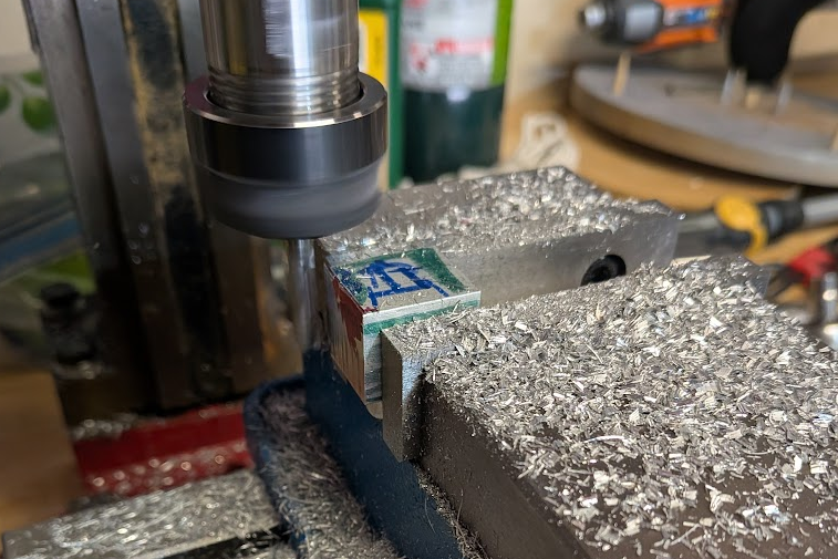
My next step after welding was to mill the inserts keeping the shelf rigid when deployed. I wasn’t sure if I wanted to machine them on the CNC router or manually, so I modeled it in Solidworks beforehand and, when I decided to do it on the mill, printed out a part drawing to keep track of dimensions and tolerances. These were fun to make, and I used a new vice after some safety concerns with my custom one.
Woodworking
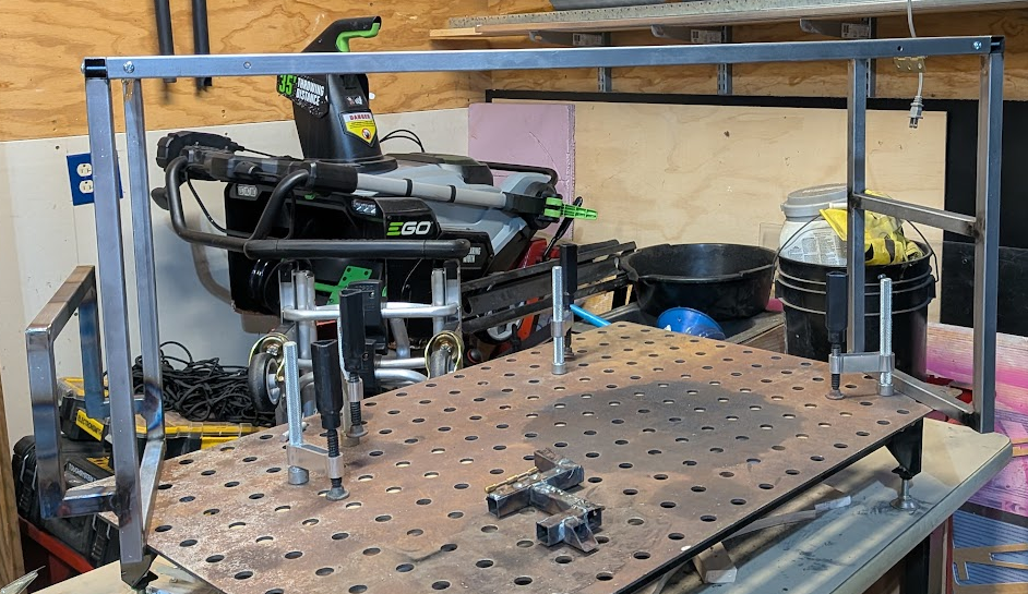
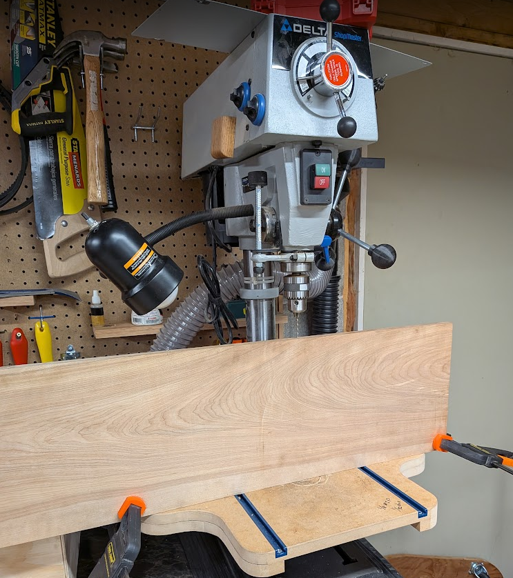
After milling the inserts, I test assembled the frame and verified the dimensions for my plank. Originally I thought about making it float like my bookshelf, but I don’t want anything I set on top to fall through so I made it flush to the tubing. Not flush on top though, as I planed down the wood so that the top face is inset below the frame for aesthetics and a lip to retain anything on top. To mount it, I predrilled some screw holes. The first couple I drilled by hand, but I switched to a sketchy drill press setup to get a bit more consistency
Assembly and Finishing
Again, I test assembled everything before taking the next step. I also added holes for screwing the hinges to the wood while it was bolted together, which let me see it in is collapsed state for the first time.
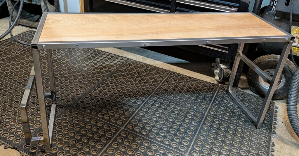
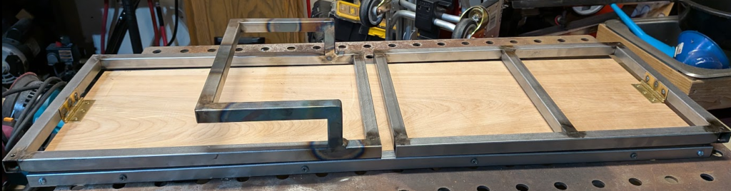
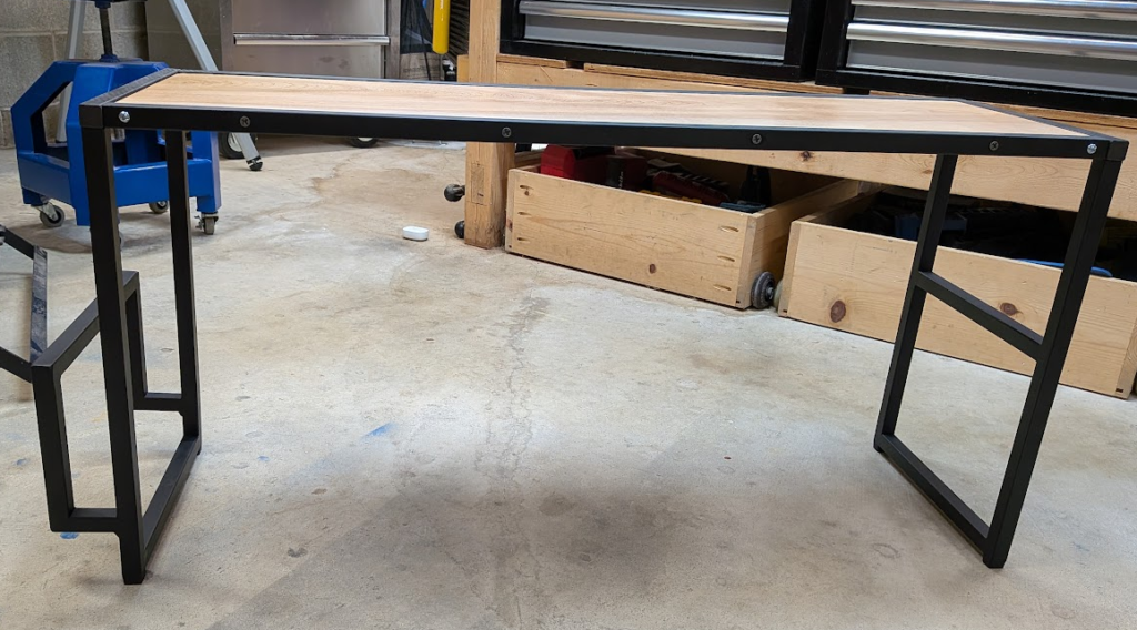
There wasn’t anything glaringly wrong, so I broke the shelf back down to sections to spray-paint the steel and apply lacquer to the wood. I messed up and caused a lot of smudges and imperfections in the paint, but I was able to sand it down and reapply paint to fix it up.
Accessories and Finishing Touches
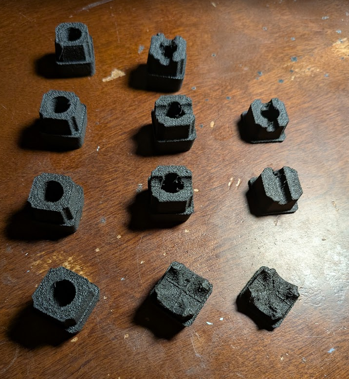
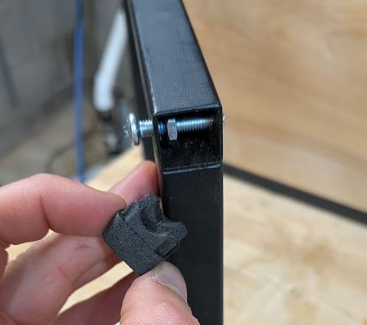
I do not want the large piece of steel furniture I just made to scratch up my desk, so I 3D-printed soft feet out of Siraya Tech’s foaming TPU to avoid that and help level the shelf. The TPU is able to print at different durometers based on print settings, which I tried out and settled on 65A for maximum compression. I tested infill levels and sizing for press-fitting into the tubes until I got it right, then moved on to making endcaps for exposed openings on the side of the legs. These needed a cutout for a bolt, but I later expanded the cutout to accommodate a nut loctited on the inside of the tubing that keeps the bolt attached even when the shelf is collapsed. To tighten and adjust this nut I had to machine a custom wrench and file it down after I got the sizing wrong.
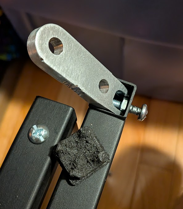
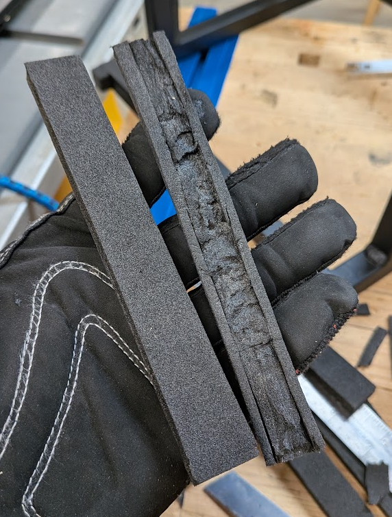
In addition to foam-like tube caps, I put foam strips on the inside of the handle where my laptop will be stowed to prevent scratching it. I tried out cutting a channel in the foam to hide the tape that secures it, but I don’t have a way to do it cleanly so I just kept the strips as they were.
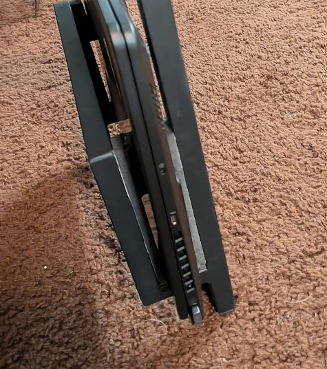
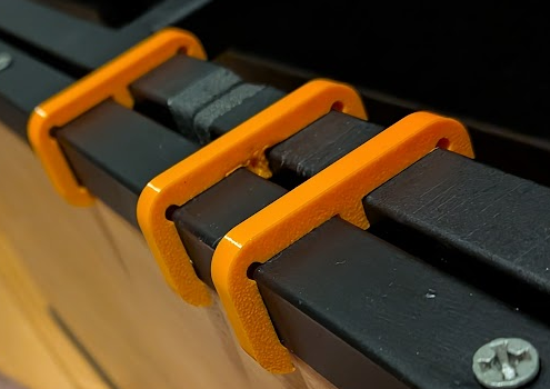
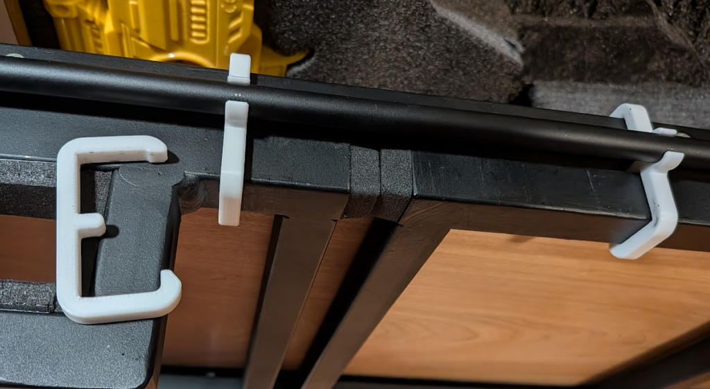
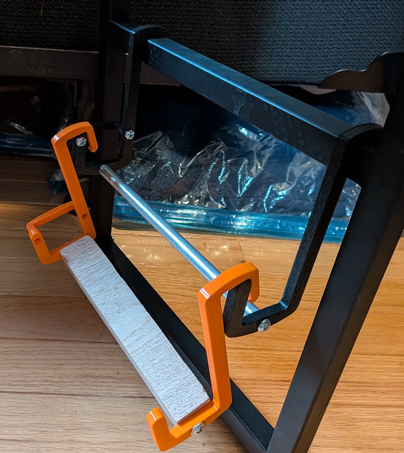
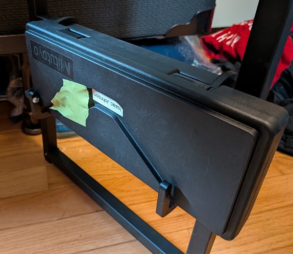
Next, I made clips that lock the shelf in its collapsed state for transport. They’re pretty simple and only took a couple iterations, but I had to switch my material from PETG to solid PC filament to stand up to repeated use. I also made another version with a clip for a support bar so all the parts of the shelf can stay together when collapsed.
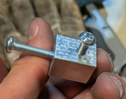
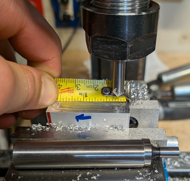
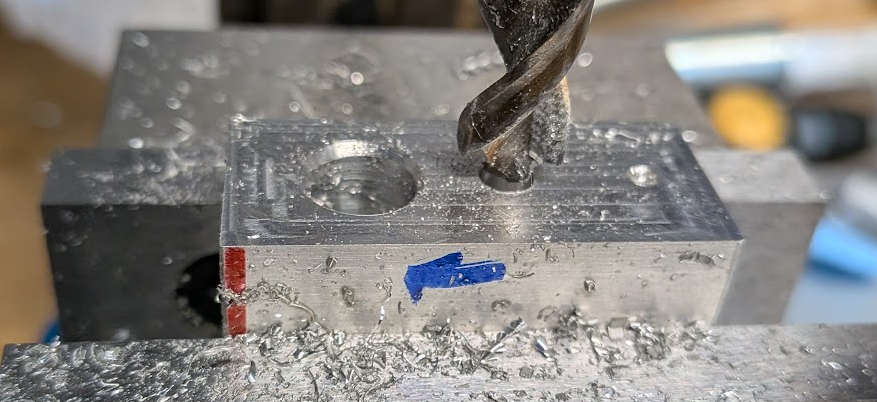
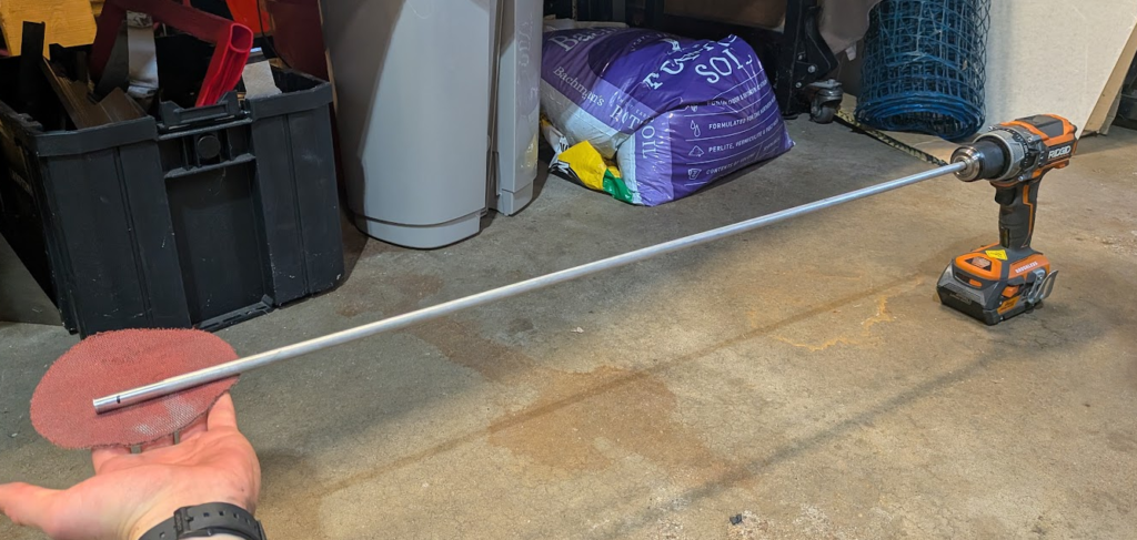
Speaking of that support bar, I realized that I needed one to increase rigidity in the shelf and decrease back and forth rocking when deployed. I started out trying to attach it magnetically, which required me to tap the ends of 3/8″ aluminum rod as that’s the best stock I had on-hand in a long enough segment. To help me tap straight, I machined a jig out of some aluminum I pulled out of a UW dumpster. First cut a chunk off on the bandsaw and faced down the sawed edge, then I used a new edgefinder to set my dials to zero relative to one of the corners of the work piece. I then drilled holes all the way through for a predrill, #6-tap-sized drill, and #6 clearance hole before counterboring each hole for the rod to seat into. Next I flipped the jig on its side and put tapped holes to dig a bolt into the rod to keep it in place during use.
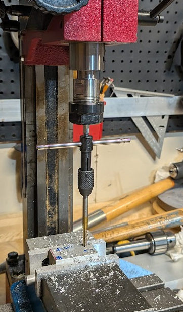
Using the jig, I drilled and tapped the rod for a 6-32 bolt and screwed magnets onto both ends. I then tested the bar on the shelf to see if it improved its rigidity, but the magnets were too weak to do anything.
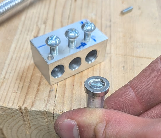
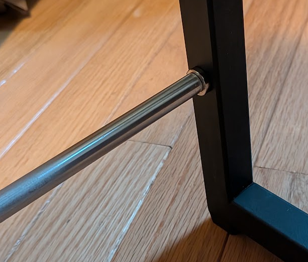
I knew bolting the rod through the legs would work, but had started with magnets to avoid drilling through the already painted shelf. I drilled out the rod ends and jig for a #10-32 tap then added a hole to the back of each leg. This hole was placed just above the back feet for the largest moment arm, but it also meant I needed to make a special foot to accommodate another captured bolt and nut. I also needed to add a spacer between the rod and leg since the magnets were 1/8″. Lastly, I sanded the rod down for painting in a safe-ish manner.
The last accessory I’ve made, so far, is a hanger for my calipers. Some prototypes led me to a press-fit in the back holds the calipers nicely but allows them to be easily put in and removed, as well as a finger on the hook that limits rocking with such a thin part.
Wrap-up
I tried a lot of new techniques with this project and it’s pushed me to improve my tools, which I’ll cover in a different post. I haven’t milled with steel before, and trying it out on a manual mill has given me the confidence to start testing on the CNC. My comfort and abilities on the manual mill has also improved through the practice I’ve gotten milling, drilling, and fixturing.
Moving away from machining, I’ve practiced my welding setup skills and patience with all of the prep work I did. Part of the reason I did so much prep work was a fear of the perceived permanency of welding and any mistakes made, but still making mistakes like having the handle of the shelf be misaligned and at an angle and having to fix those helped me get over it. Same with painting, where I had to sand down and fix my mistakes.