I’ve been designing a music stand to keep myself busy after my semester ended. Since I don’t have a cello to play anymore I don’t have the motivation to fabricate it, but it’s been a good exercise in practicing what I’ve learned at UW-Madison and to improve my modeling/Solidworks skills.
Ideation
Recently I’ve really wanted to get into playing the cello again, and that got me thinking about music stands. Steel flowers have also been on my mind after I made a couple more over spring break, so I combined the two into a concept inspired by structures designed for vines to climb on. The thought behind my drawings is that a music stand would serve as a great structure to support a steel rose vine sculpture, even more so if it was modeled after a trellis meant to support actual rose vines.
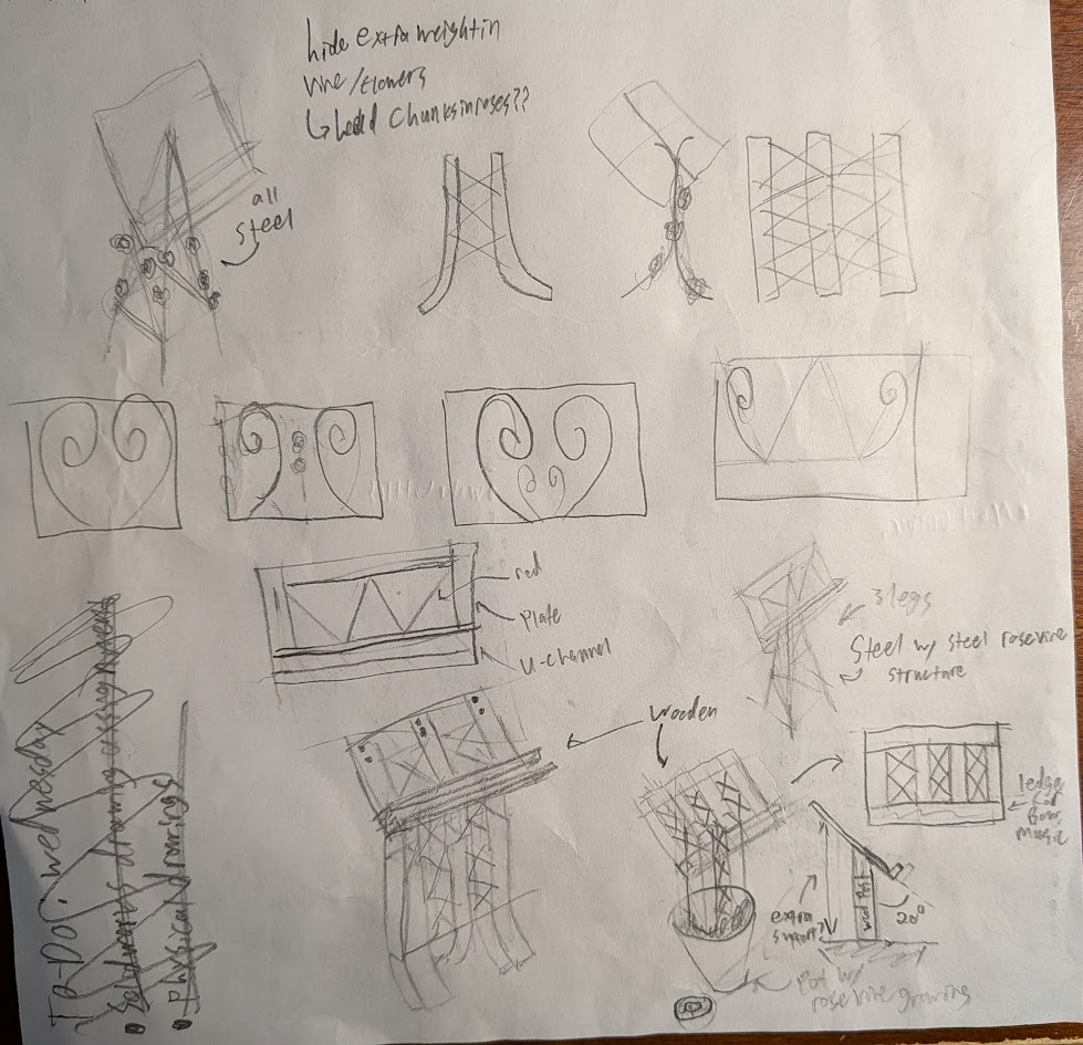
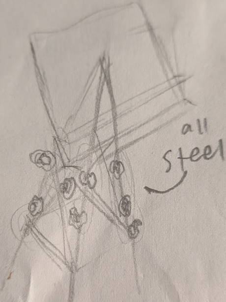
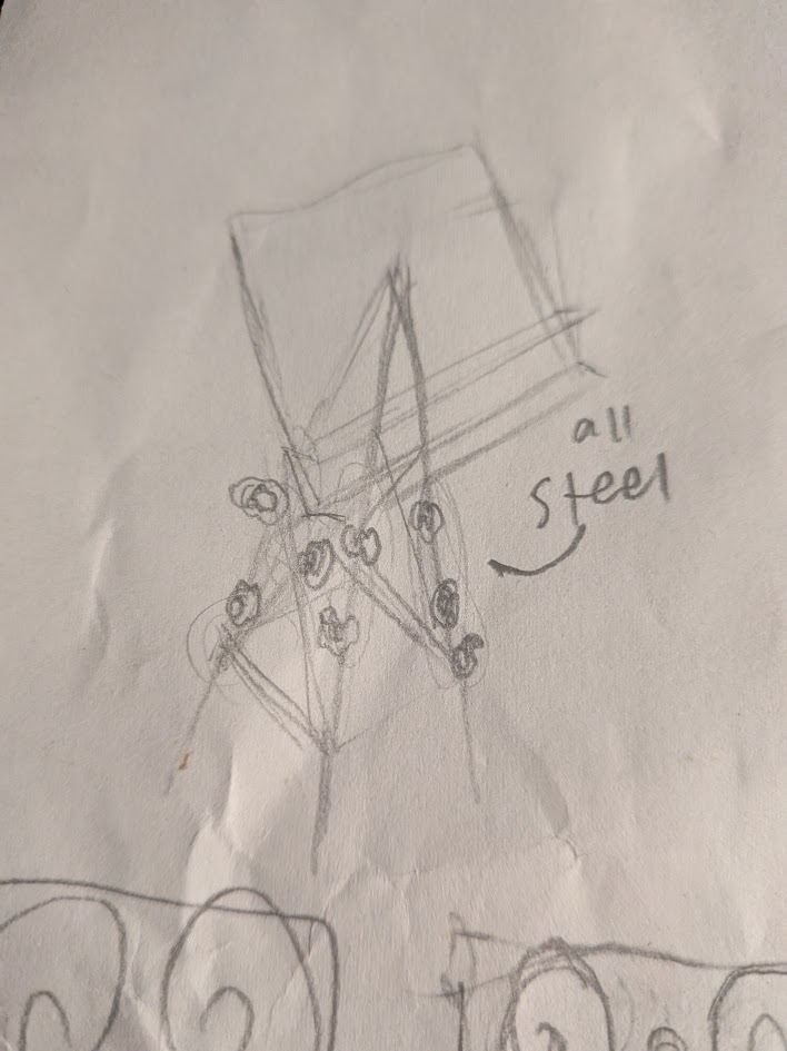
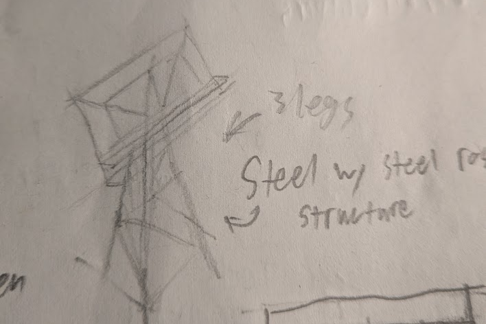
One of the two options I landed on was a pyramidal structure made of steel rod, modeled after pictures of free-standing trellises I saw online. The legs of the structure meant to support the vine and music-holding backboard would be thicker steel rod, while cross members preventing the legs from splaying out and creating more space for the vine to hang from would be made up of thinner rod. Initially I planned on mounting the backboard on the plane formed by the front legs, sitting at the angle they made with the floor.
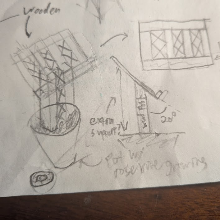
The other option I considered was a flatter structure inspired by trellises that require a wall to lean on. This option could be made of steel, but seems better suited as wooden. I’d have posts come up with wood dowels or strips of wood crossing between them and would consider anchoring the posts in a pot growing an actual rose vine as suggested by my dad.
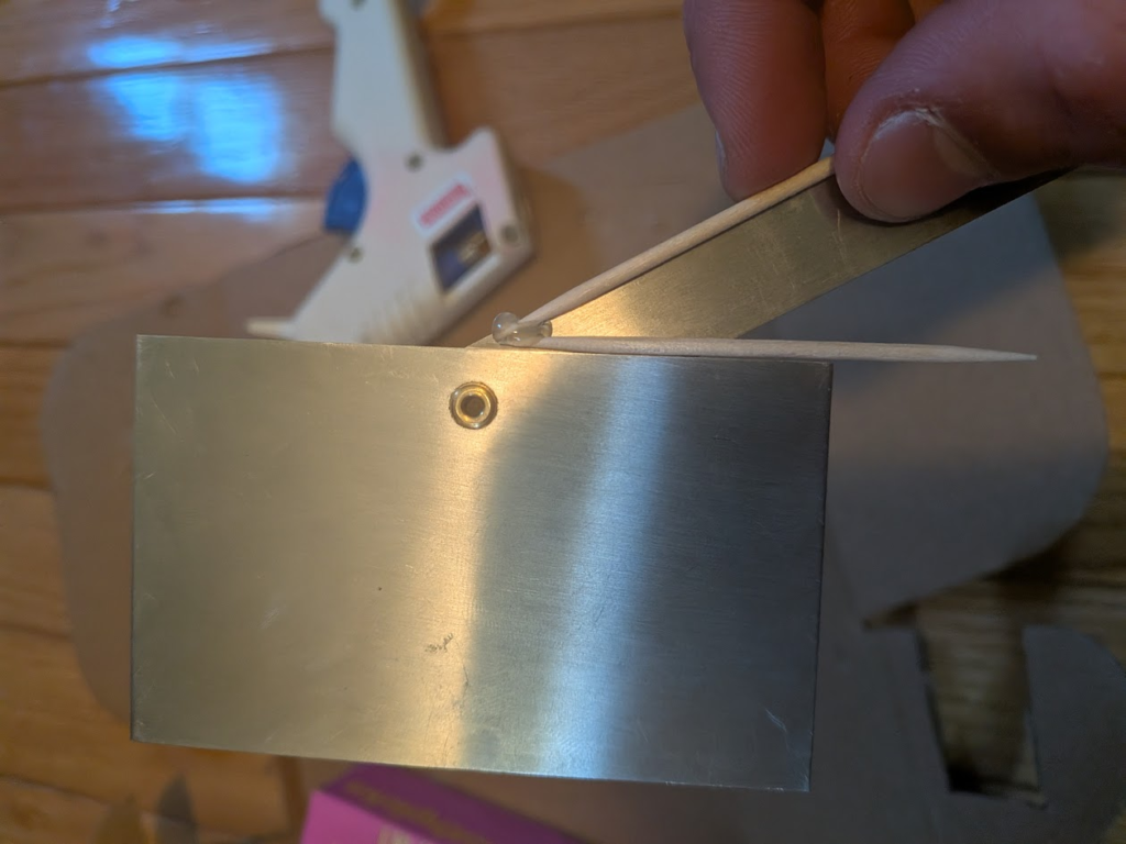
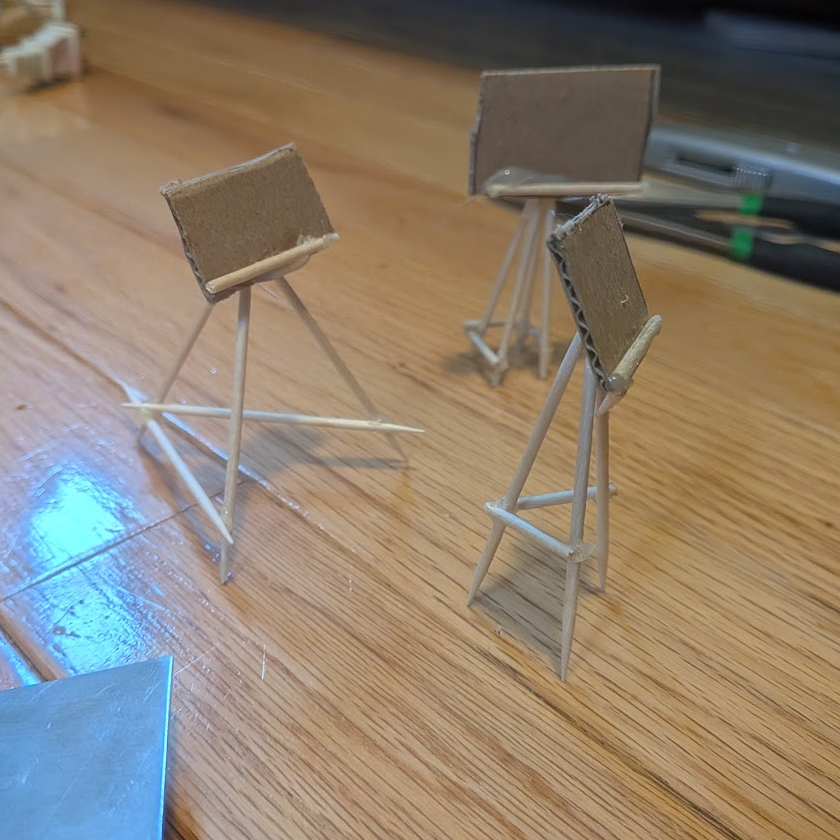
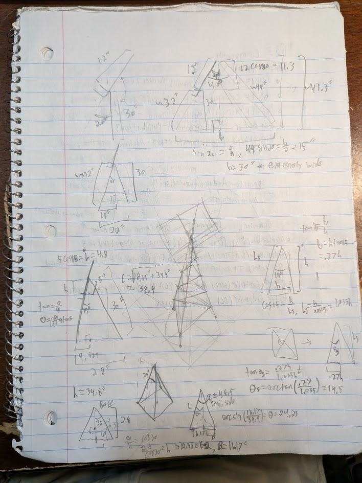
I evaluated both designs with some math and research to decide which I would go forward with. The thought of actually growing a vine on the wooden option was killed by looking at pot dimensions and soil volume requirements to grow different species of climbing roses, which left me doing some trigonometry and physical modeling to figure out how to make the pyramidal options work. Using the setup below, I made toothpick-and-cardboard models based on combinations of parameters to quickly visualize concepts at a 1:25.4 scale. To keep my lengths and angles correct, I marked dimensions using my calipers and used the straight edges of a locking angle measurement tool as a jig to glue toothpicks together accurately.
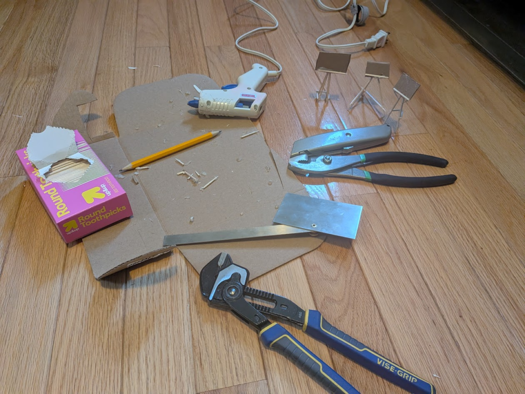
Of the models I made, two had triangular bases and one was square. While the square version would be simpler to do calculations for and theoretically more stable, I worried about the feasibility of keeping the feet level and in general preferred the triangular options. For the next model, one with a triangular base, I calculated the required angles to mount the backboard directly to the legs at a desired angle which looked ridiculously wide. To maintain both a narrower base and a larger backboard angle, I added supports that pushed the base of the backboard off the plane formed by the front legs forming a new plane at the correct angle.
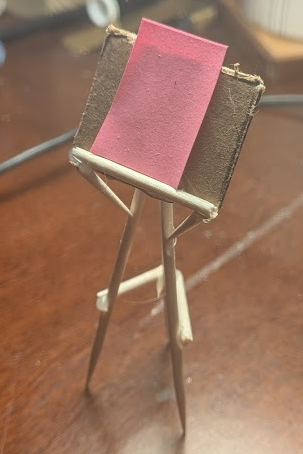
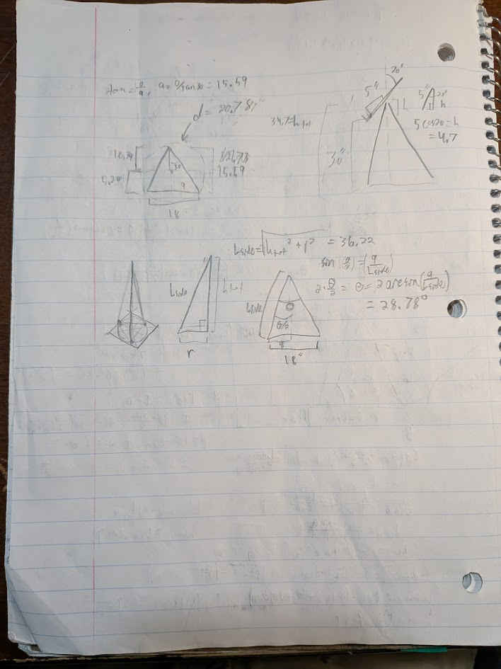
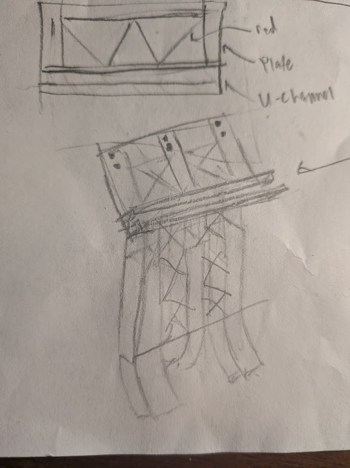
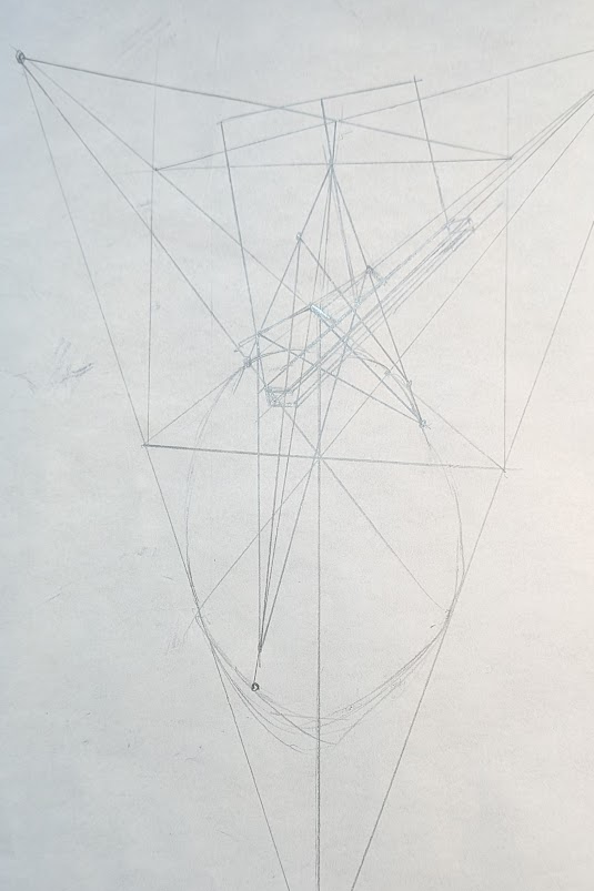
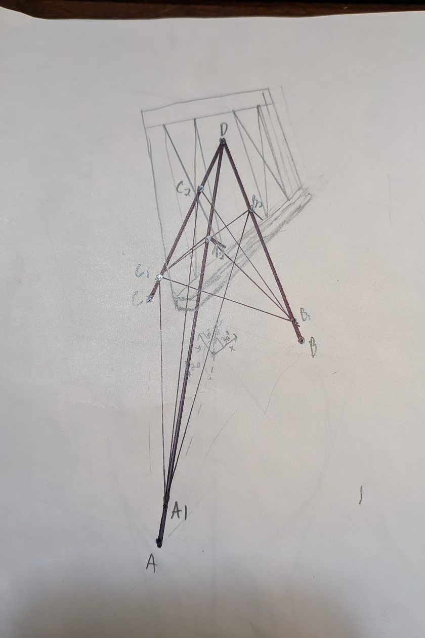
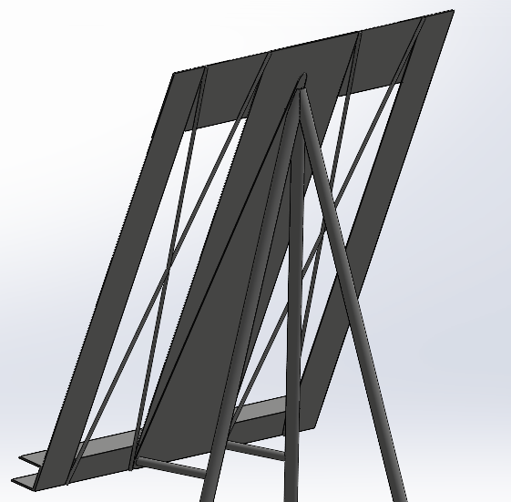
With a model that I liked, I made a final sketch of the concept in perspective. My plan was to have a two horizontal braces mounted a small amount above the floor, then have cross braces that originate same places the horizontal braces do on the the legs. The support bars pushing the backboard to the correct angle then would originate at the intersection between the other end of the cross braces and the legs, coming perpendicularly off the latter.
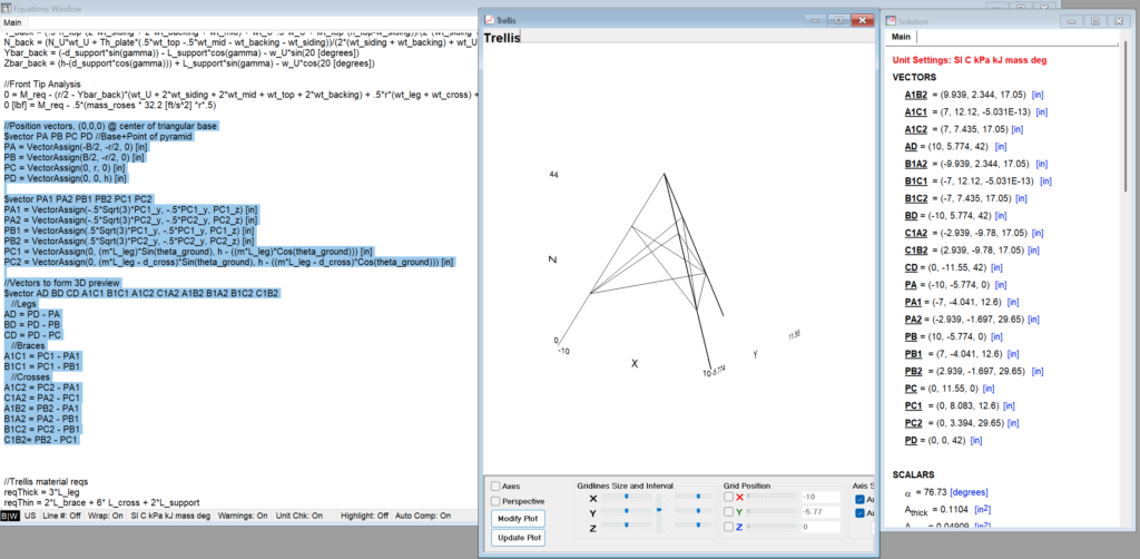
Parametric Definition for the Trellis, Transferring to Equation Solver
For each of the models I made earlier, I had went through the whole process of sketching out side views and doing calculations from scratch. For the actual design, I figured I’d rather have it all defined off of a couple variables. That way, when something eventually needed to be fixed or updated it would hold up. To start my key variables were base width, trellis height, and a scalar value to determine how far up the height of the trellis to start placing bracing. Later I added parameters for the backboard, and even later made the angle between the cross braces and horizontal brace a parameter.
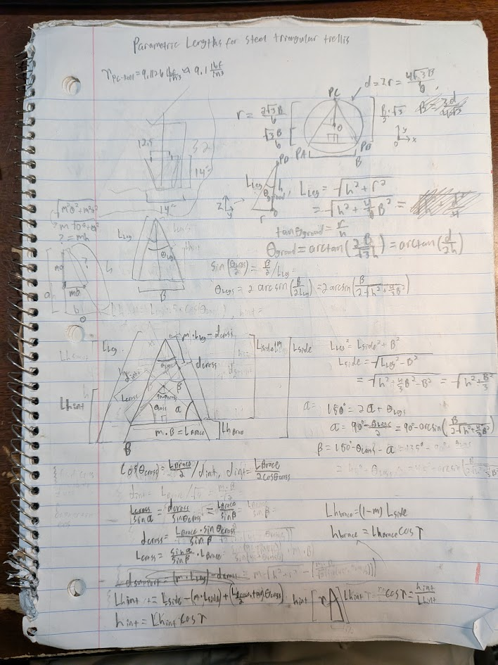
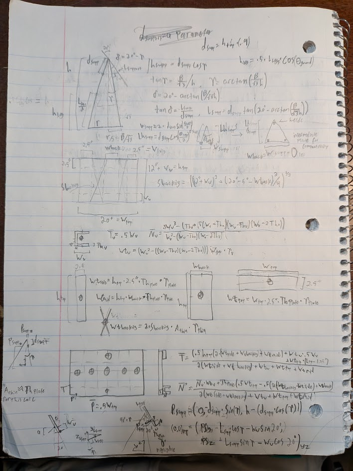
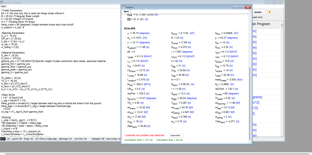
Working my way upward from the base, I used the sketches I drew to define the lengths of each member and the distance up the legs that they connected at. When I was done with the trellis, I also worked on figuring out dimensions for a backboard and where its center of mass was relative to the center of the base. As I went I added calculations to my equation solver file in addition to materials parameters I’d use to determine whether or not the trellis would tip. This software is what I used in my Statics class and will keep coming up in mechanics courses, so I figured it wouldn’t hurt to practice with it.
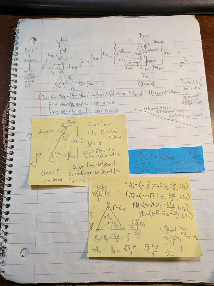
I got weird results from my tipping calculations, which led me to check my math and to modify parameters to get accurate results and, when I did, to determine how to prevent tipping about the front of the stand. My key requirements for the stand is that it doesn’t tip, has a reasonably narrow base, and that the backboard is at a certain angle and height, which I kept in the back of my mind as I worked.
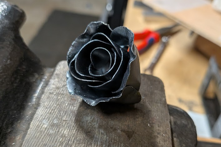
Initially I calculated that I needed 15 pounds of steel rose vine sculpture to keep the stand stable, at which point I took an excuse to make my another steel rose to figure out how much it weighed and, consequently, how many I’d need. This was the third rose I’ve made and I try something new every time, so I attacked the edges of the last layer of petals with a pair of pliers to flare them out like I’ve seen others do online. Most of the examples I’ve seen have been shaped using a torch and pliers, but when I tested that on a cutoff the steel I’m using (which is thin enough to bend cold) breaks off a ton of scale and would require sanding after being bent. Anyways, the flower was only .1lb so I’d need 150 roses if I went ahead with the values I was using. That seemed extreme, so I modified my parameters such as backboard thickness and base width until it could stand reasonably on its own.
At the same time I worked on tipping calculations, I also made a vector plot of the trellis to visualize it and to act as a sanity check for my calculated values. To ensure that the music stand was tall enough, I used the Z coordinate of the top interface for the cross members as the rough height of the backboard and tweaked relevant parameters to achieve a comfortable height for reading sheet music. Having position vectors for points on the trellis made it simpler to find centers of mass too.
Modeling In SolidWorks
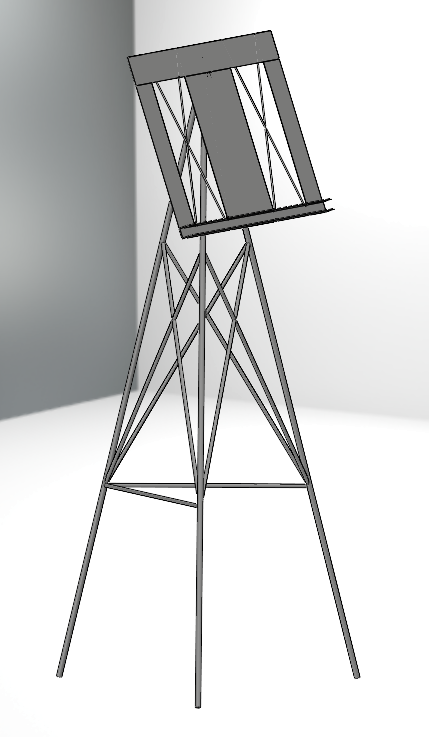
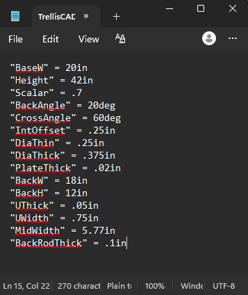
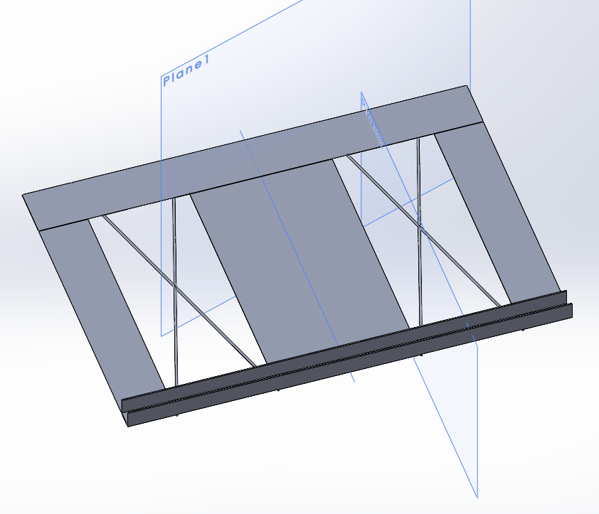
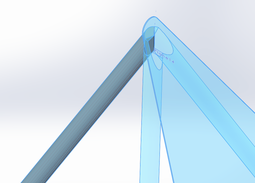
Once I was done in the equation solver, I moved to Solidworks. To start, I made a text file with key variables that I could import into part files then used it to create sketches depicting the trellis. To make solid geometry, I created planes perpendicular to each length of rod and used the lines as guides for extrusions.
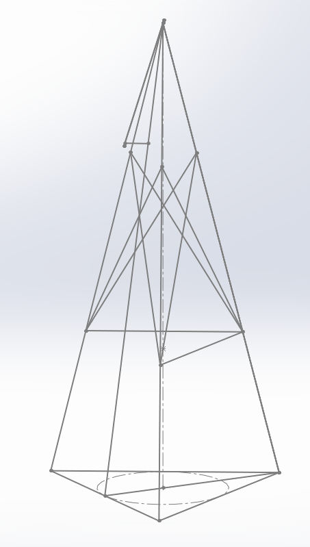
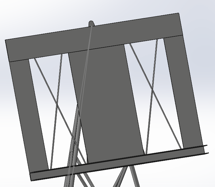
My original thought for attaching the backboard was to just directly weld it to the support rods and top of the trellis, but I added a plate I can screw the backboard on and off of since I have to move the stand back and forth from college if I ever fabricate it. As such, I made a separate part file for the backboard and used an assembly to put them together. For simplicity, and since both components would be welded, I made the trellis and backboard each a single body rather than have part files for each individual component
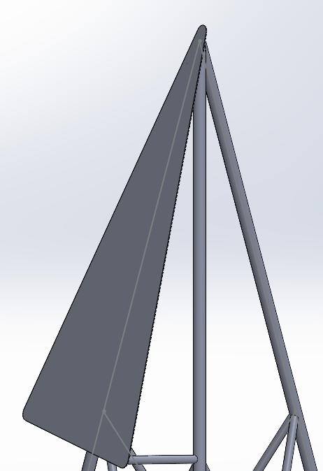
Assembling the two components, I noticed that the top of the backboard mounting plate stuck out above the backboard with the parameters I was using. This was due to the location of the supports for the backboard being tied to the cross supports, so I went and updated my drawings and equations to remove this dependency before updating the CAD.
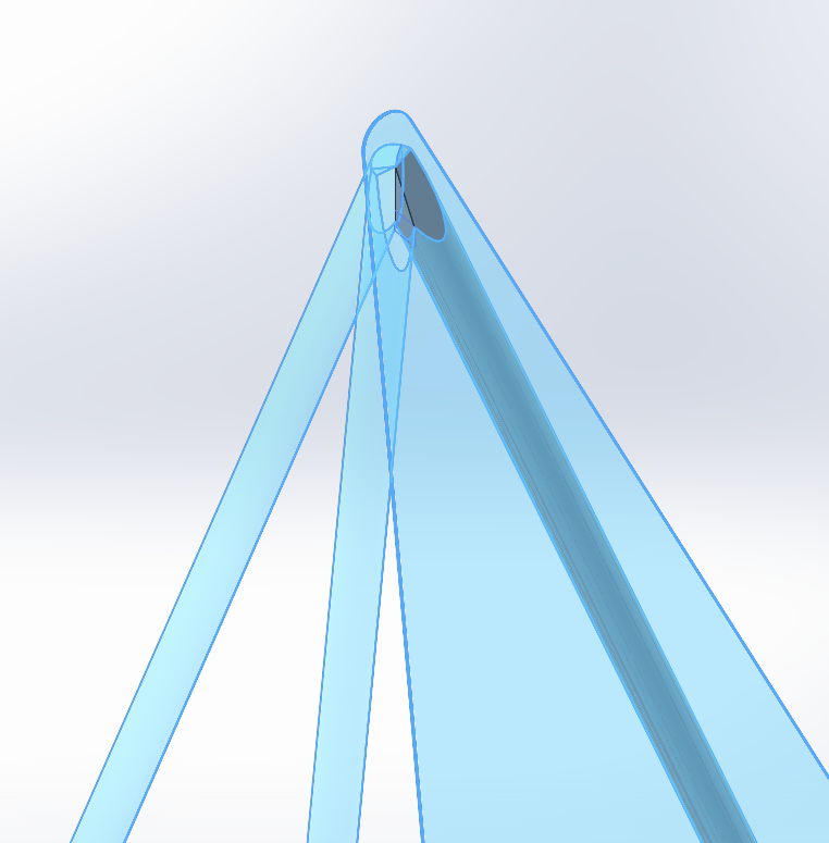
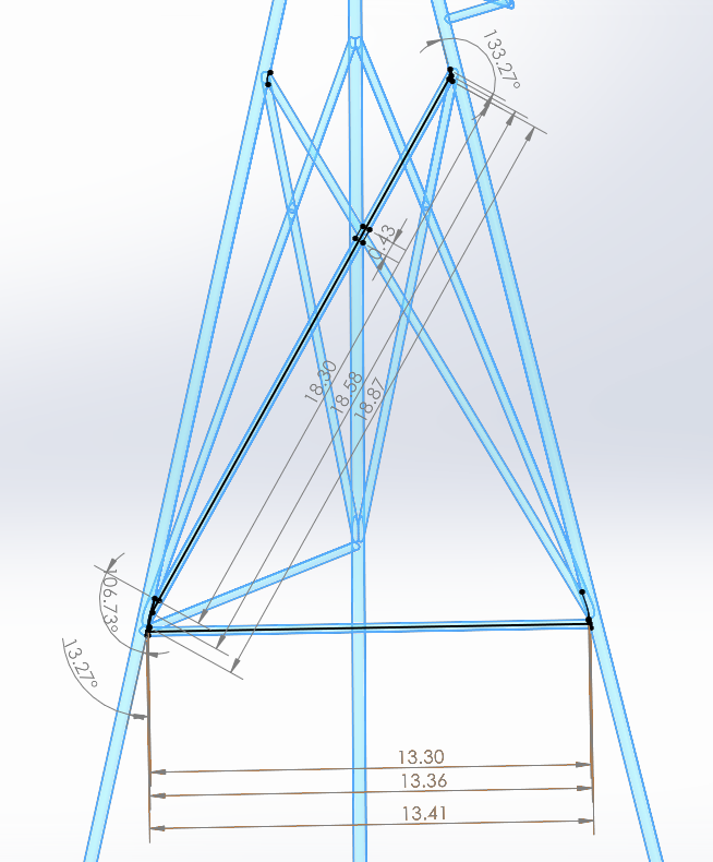
To figure out what lengths and angles I’d need to cut rod at for accurate assembly and welding of the trellis, I made a copy of my part file and cut up the solid body. I used the split tool and planes formed by intersection of the legs to isolate each leg, which gave me the end-geometry needed to interface with each other and the mounting plate. As for the supports, I projected their intersection with each other and the legs into a sketch and found the lengths and angles needed to cut each support, including a slot I’d put in the middle of each intersecting cross support so they don’t interfere with each other.
At this point I was ready to buy material and start preparations for welding the trellis and backboard but had been running out of interest in the project. Without a cello, I’m not too interested in a music stand; as such, I’m leaving it at the end of the design phase for if/when I’m ready for it.
Takeaways
Even though I haven’t actually made the stand, I got good practice and learned things from the process of designing it. All of the calculations I did were set up by hand using sketches and trigonometry, making this a project based on math and hand drawings. I also applied what I learned in my engineering classes such as perspective drawing to communicate concepts, sum of moment calculations, and the use of equation solving software. This was also a good opportunity to practice in Solidworks, where I got familiar with its workflows and tools that differ from the CAD software I’m more comfortable with. Lastly, I tried out quick physical modeling to validate ideas and physically test geometry for the first time and will likely do so again in the future.