A while ago I wanted to make a Pip-Boy-inspired, wrist-mounted computer out of a Raspberry Pi, but I didn’t have the skills. I probably don’t have all of them still but over J-term I adapted a concept I had for controlling a cursor into a custom mouse.
Controls and Balancing Complexity
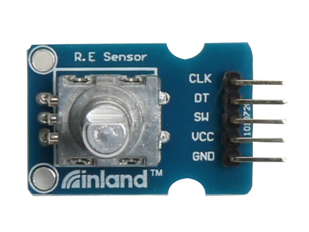
The main feature of this mouse are the rotary encoders I used for mouse movement and scrolling. This control scheme has been in the back of my head for years, partly because of the ease of packaging it on a wrist computer and partly because of the unique control provided. A trackball or trackpad are also pretty easy to package, but they don’t have the same functionality or novelty. Turning a rotary encoder can be mapped onto forward and backward movement along a single axis, which allows for pixel-precise cursor movements where other forms of mice are realistically limited to larger compound movements. Single axis control isn’t too useful, but it’s a fun approach and more importantly lets me get perfect placement on a monkey-themed tower defense game. Below is a picture of the encoder module I bought from microcenter to help me achieve this goal.
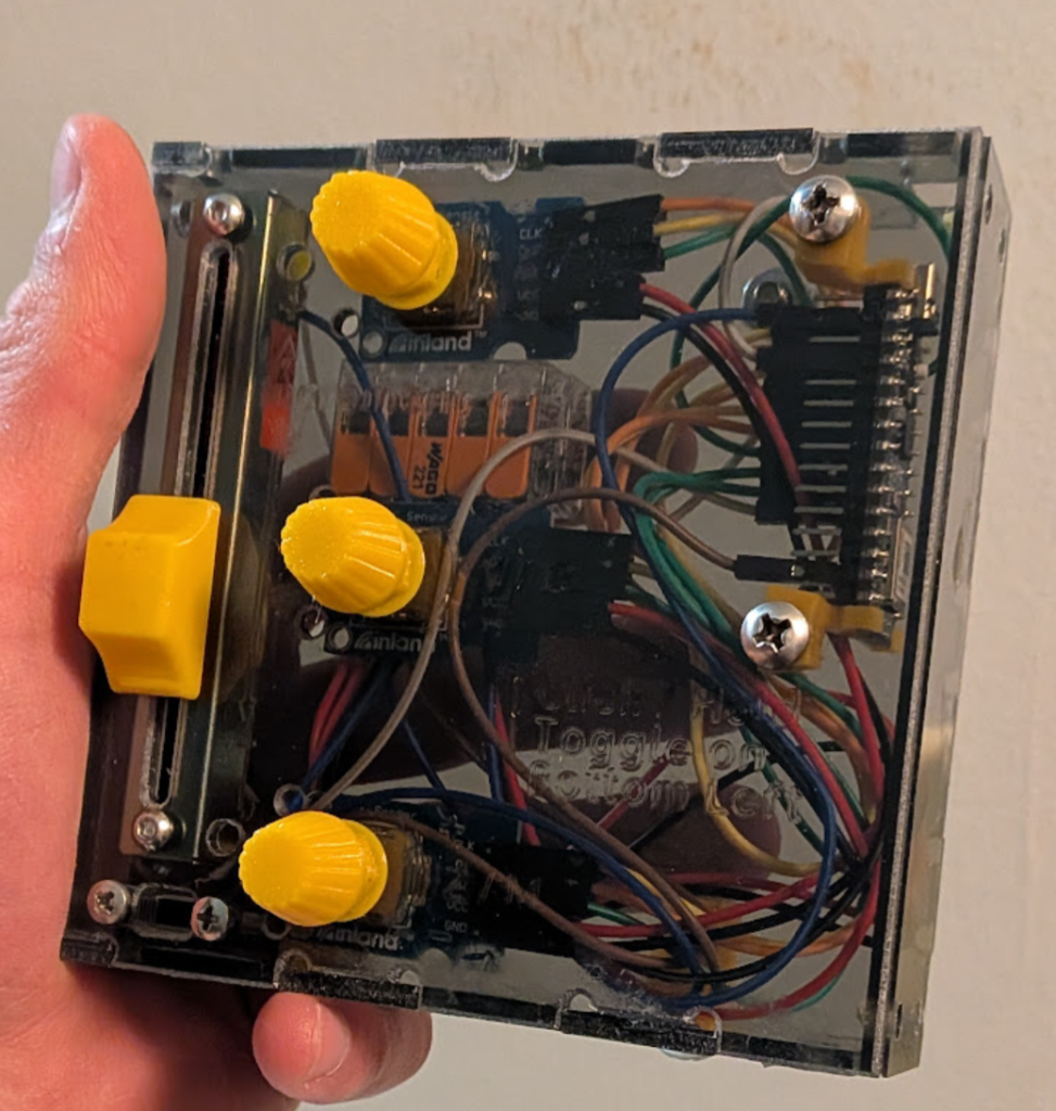
As I said above, this mouse is intended to allow for pixel by pixel movement. For normal use it’s a bit extreme to turn a knob hundreds of times to move across a screen, so I included a slider that modifies the distance the cursor moves as you turn the encoder. This helps the mouse be less painful to use, allowing adjustment between fine and coarse movement on the fly.
Of course, how you move a cursor isn’t the only important aspect of a mouse. Ideally it can, well, click on things you move the cursor onto; for this functionality, I used the Inland encoder’s built in push button for left, middle, and right clicking. Each button sends a single pulse even if held, which was an intentional choice. Pushing down a knob and turning that same knob at the same time is really awkward and makes it easy to accidentally let go, so to allow for click-drag functionality I added a toggle switch to determine whether button inputs send single click or hold/release signals. I could’ve added extra buttons for each toggle, but they would have been just as unintuitive and would have required more code plus extra wires.
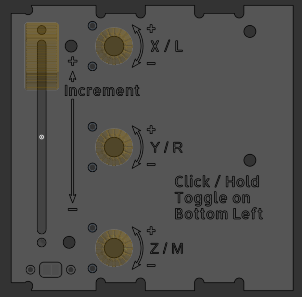
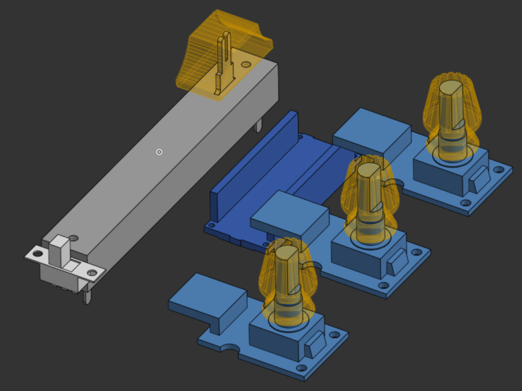
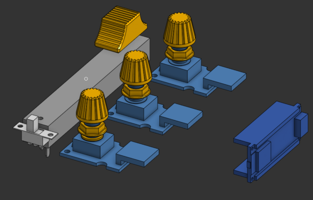
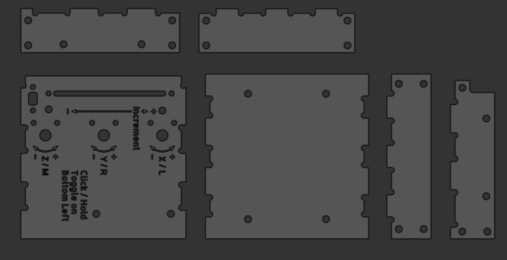
You can see the control scheme overlayed on part of the model mouse case model below, which I etched labels onto for ease-of-use. In real life I inverted the X control, but otherwise the graphic is accurate.
Working on Wiring and Code
(Link to the final code if you’re curious)
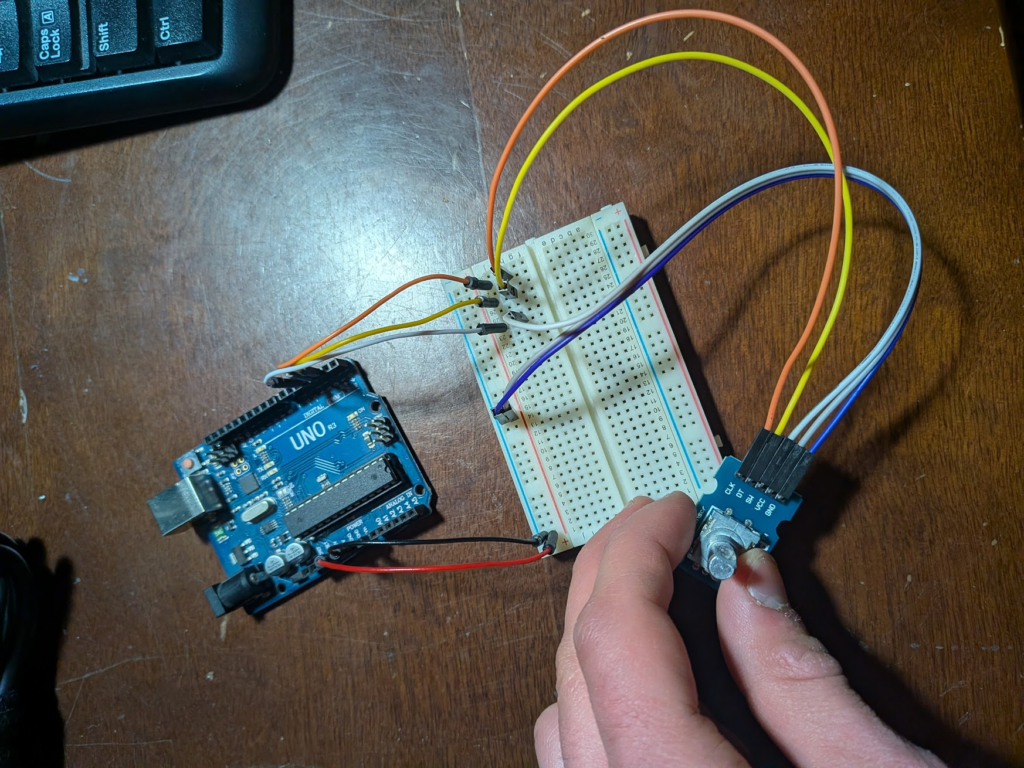
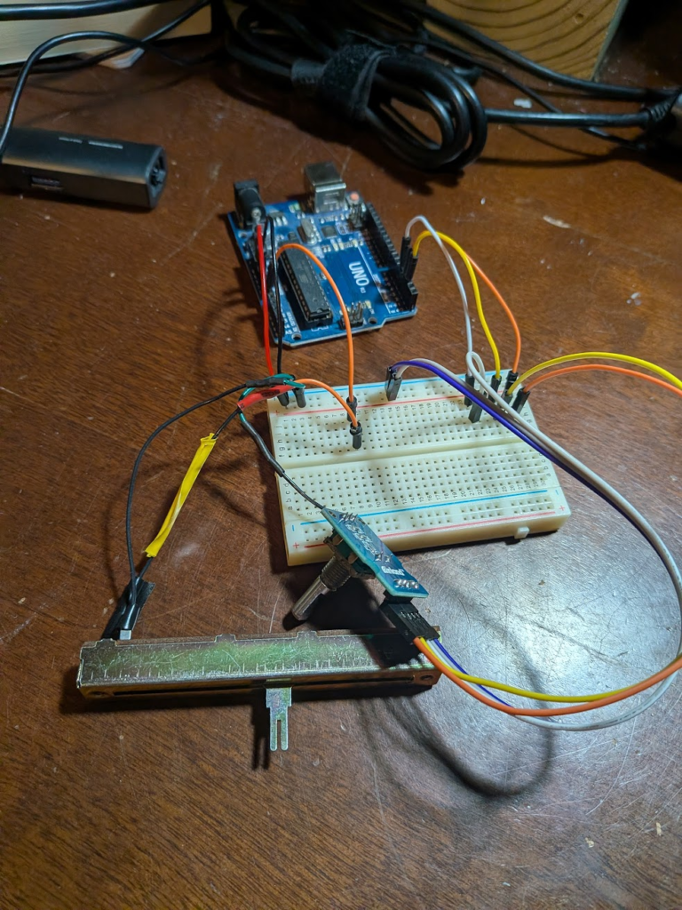
My first step once I had my hands on the encoders and a slider was to get the rotary encoders working before I got my hopes up. In order to break up the task into manageable chunks, I focused solely on figuring out how to consistently read just the direction just one encoder turned off of an Arduino Uno; originally this direction was indicated by a flash from an LED, but for the sake of my eyes I switched to reading serial output.
The first of many methods I tried to read the output of the encoder was through polling the encoder for a signal sent from the CLK pin. This approach was based off of a page from Arduino’s documentation I can’t find describing the workings of an encoder. My understanding of their working principle is that when the knob is turned, a plate with slots in it rotates with it and presses against clock and data contacts that normally sit in its slots. This completes a circuit and sends a signal through the respective pins, and the order the signals come in tells you which contact was touched first, corresponding to the direction the knob turned. In practice, the CLK pin sending a signal triggers the DT pin to be read and whether it’s high or low tells you direction – or it should. My biggest issue with this method was that my output wasn’t consistent and was biased towards the DT pin being read as not sending a signal. I tried adding and removing delays, polling DT rather than CLK, polling both, using a fresh encoder, etc. but kept getting the same issue. To be frank, I don’t have the knowledge to diagnose the problem.
void loop() {
  digitalWrite(ccwLED, LOW);
  digitalWrite(cwLED, LOW);
  int xClkState = digitalRead(xClk);
  int xDtState = digitalRead(xDt);
  if(xClkState != priorXClkState && xClkState == HIGH){
      //delay(5);
      if(xDtState == HIGH){
        digitalWrite(cwLED, HIGH);
        cwCount++;
      }
      if(xDtState == LOW){
        digitalWrite(ccwLED, HIGH);
        ccwCount++;
      }
      }
    priorXClkState = xClkState;
      Serial.print("CW Pulses:");
      Serial.println(cwCount);
      Serial.print("CCW Pulses:");
      Serial.println(ccwCount);
      delay(0);
}
Having issues with polling, I looked more into how to read encoders and tried creating interrupt routines as well as calling MatHertel’s RotaryEncoder and StutchBury’s EncoderButton libraries. With these methods, something was causing the encoder to register as making large steps, often in the wrong directions. EncoderButton was pretty consistent if multiple interrupt-capable pins were used, but if I only used one it would send two opposite signals; the Uno only had two interrupt pins and I planned on using 3 encoders, so I kept looking for alternatives.
Taking a break from figuring out encoder movements, I worked on my sensitivity slider. After some quick soldering to plug it into a breadboard, I used an analog pin to read its value and Arduino IDE’s map function to make the output easier to use. To check that everything worked I just printed the mapped value, but later on I’d use this as a magnitude along my X-Y-scroll axes.
const int pinSlide = A0;

void setup() {
Serial.begin(9600);
while (!Serial);
}

void loop() {

int slideValue = map(analogRead(pinSlide), 0, 1023, 1, 2400);
Serial.println(slideValue);
delay(100);

}
After looking a bit more into libraries, I took a break to work on a more-tangible project. When I came back to the mouse, I looked into Paul Stroffregen’s Encoder library that others kept referencing. They allowed for both polling and interrupts, and it was simple enough to get good results. A major hang-up I had was figuring out why each turn sent 4 output values, which is written about in the documentation. Eventually I found a forum post that I can’t find again with the same issue, which they solved by using a divide with remainder operator shown in the code below.
  long xNew = encX.read();
  if (xNew != xPos) {
      if (xNew % 4 == 0) {}}
With working encoder code, I put all the elements together. I used Arduino’s ezButton library for registering when the encoders’ buttons were pressed, as well as a simple check for if the toggle-switch is engaged and if the cursor is actively being “held” on each button. I copied this code for right and middle click functionality.
in void loop(){
 int toggle = digitalRead(togglePin);
  if(buttonL.isPressed()){
    if(toggle == HIGH && lState == 0){
      Serial.println("l click toggle on");
      lState = 1;
      Mouse.press(MOUSE_LEFT);
    }else if(toggle == HIGH && lState == 1){
      Serial.println("l click toggle off");
      lState = 0;
      Mouse.release(MOUSE_LEFT);
    }else if(toggle != HIGH){
      Serial.println("L Click");
      lState = 0;
      Mouse.click(MOUSE_LEFT);
    }}
I also added copies of the X-encoder reading code to test having multiple encoders and including the slider’s multiplier. Before testing by actually moving the mouse, I did the same procedure of reading the direction value of each encoder paired with the magnitude of the multiplier.
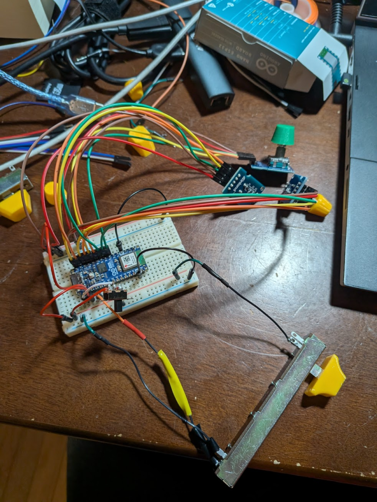
With working code I tried to add a mouse control library, but apparently the Uno can’t act as one. I needed a new board capable of HID communication over USB, of which I chose the Arduino Nano ESP32 to not too-badly over-spec and for ease of transitioning over. The manual warned of sending it signals over 3.3V, so I had to switch my sensors from 5V and tweak the mapping on the slider since it relies on measuring the magnitude of resistance through it. Besides for a few more minor tweaks and testing, the mouse was ready to be packaged in a usable form-factor
//in void().loop
Mouse.move(xChange, yChange, zChange);
xChange = 0;
  long increment = map(analogRead(slider), 0, 4095, 1, 120);
  long xNew = encX.read();
  if (xNew != xPos) {
      if (xNew % 4 == 0) {
        xChange = -(xNew - xPos) * increment/4;
        Serial.print("xChange: ");
        Serial.println(xChange);
        xPos = xNew;
      }
   }
Creating a Case and Wiring
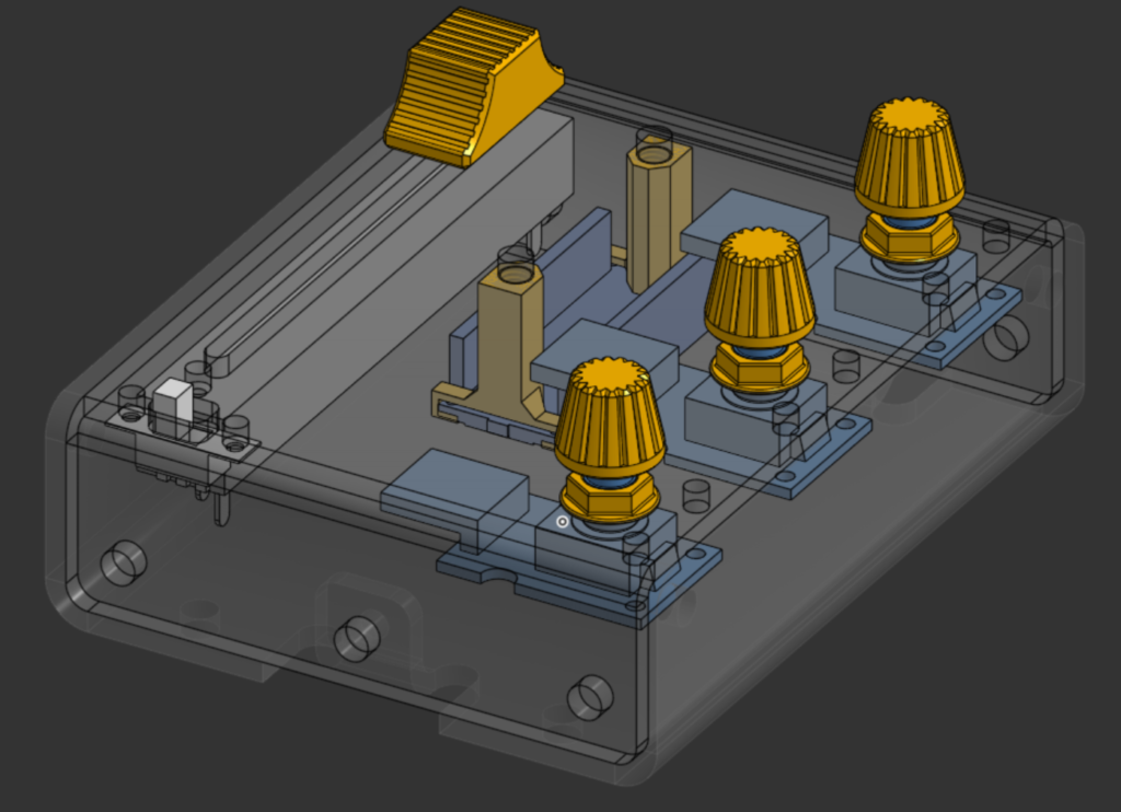
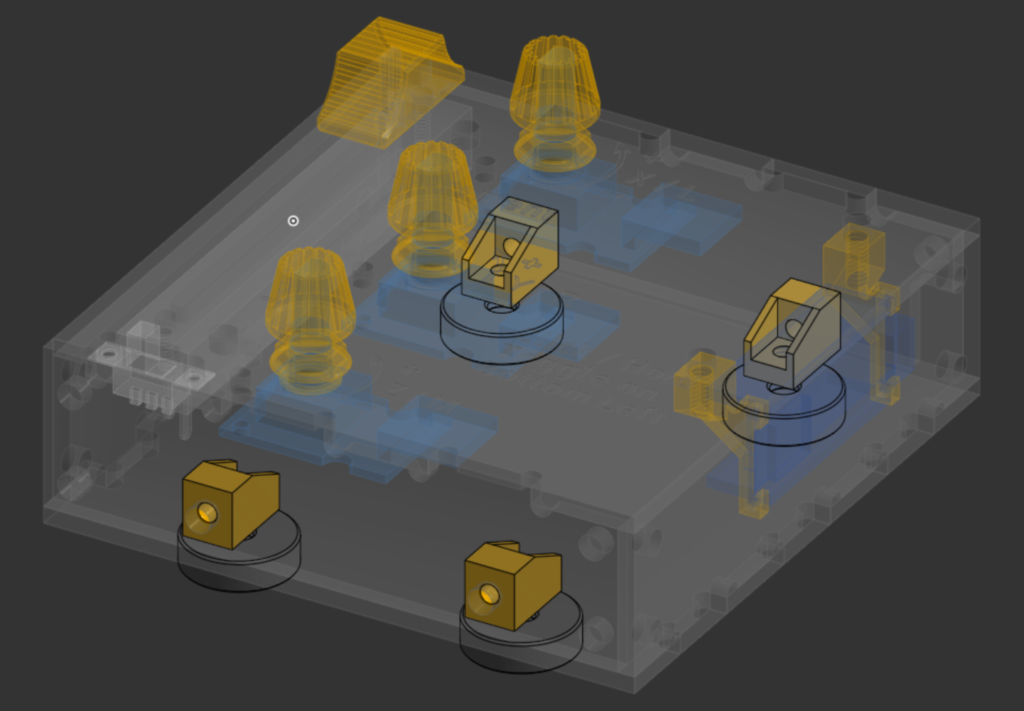
My first step in designing the case was to model the electronics in CAD so I could build a case around them. Having models to go off of, as opposed to just repeatedly measuring and inputting values as-needed, let me create an assembly laying out the components’ locations and helped contextualize the scale of future parts. To make the final product easier to use, I also modeled caps for the slider and encoders.
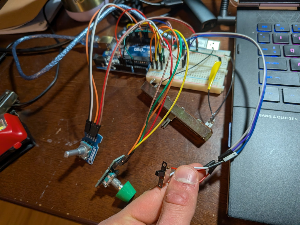
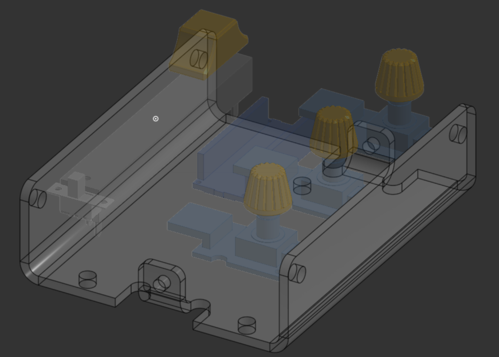
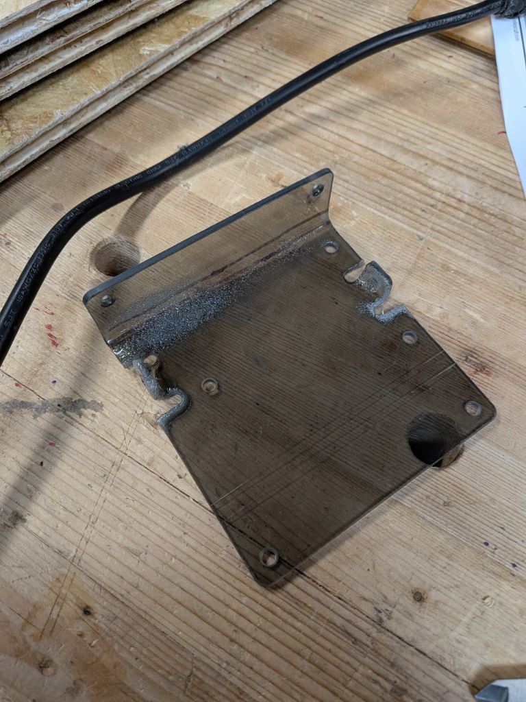
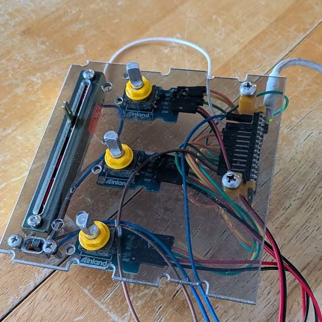
Using the layout as a guide, my initial design for a case was two bent polycarbonate plates in a compact form factor. I wanted to get some more experience designing bent sheet-parts, but I didn’t have the means to fabricate them with what I had on hand. My secondary processing consisted of blasting the plates with a heat gun and trying to bend them with pliers against angle iron, but as you can see below that didn’t work out too well.
On top of my plastic bending problems, attaching my components to the top plate showed that I didn’t give myself enough room for wiring; the ends of the jumper wires I planned on using were stuck out too much and those coming off the encoders/nano wouldn’t fit. This led me to redesign the case around a new layout, one with a bit more room to work with jumpers so I wouldn’t even have to think about soldering and accidentally damaging a component.
Having been humbled by heat-bending, I instead designed plates I could just glue together. The top and bottom plates of the case each have two side plates attached and aligned using interlocking tabs, and to join these two assemblies I added some 3D-printed parts I could thread a bolt into. One drawback to this approach is that it’s annoying to sketch out since I can’t have concave corners on milled parts to account for endmills being circular.
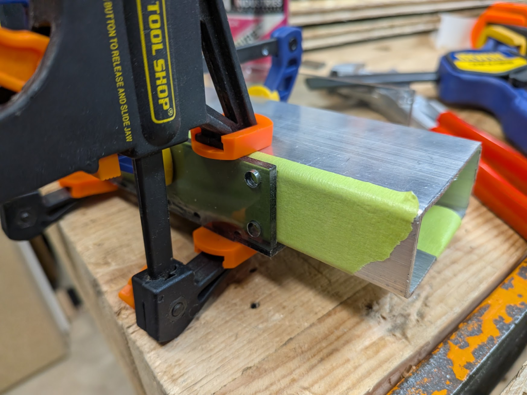
Tabs made gluing together the case easier since they automatically took care of alignment and positioning. To keep the side plates perpendicular to the top/bottom plates after applying glue and make clamping easier, I butted a 2×1 tube against the positioned plate and took advantage of the flexible fingers of speed clamps to hold both the box and the edge of the side plate. The green stuff on the tubing is painters tape meant to prevent the aluminum from scratching my pretty plastic. Also, in the future I need to be more careful while applying glue as I spattered a bit around the joints.
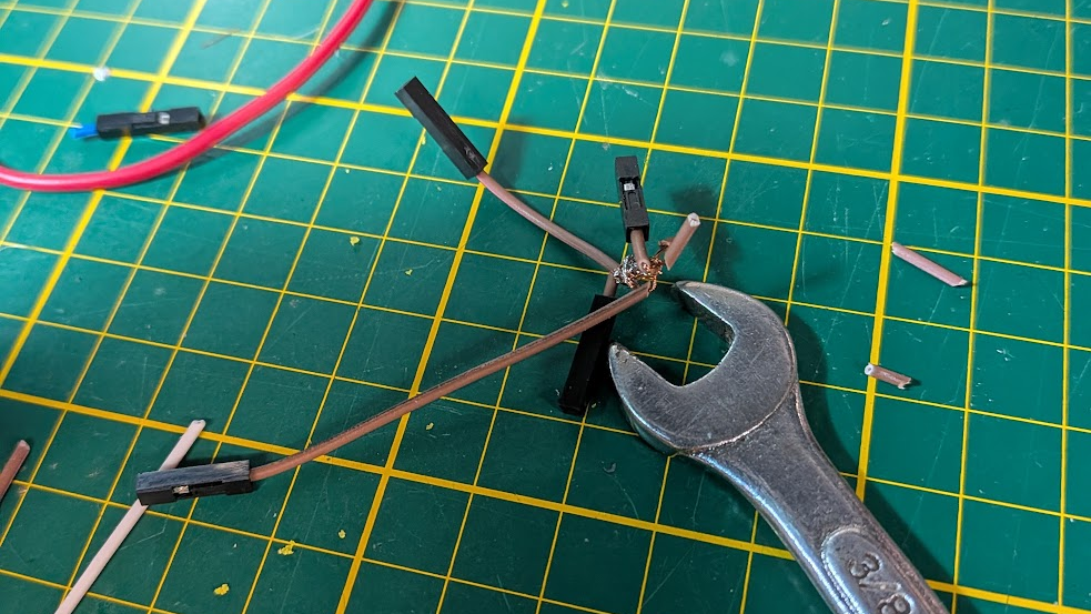
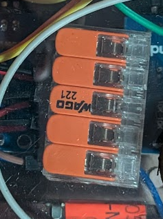
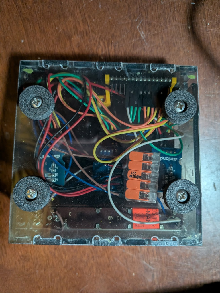
When I started wiring, I planned to splice the ends of leads together into large ground and positive chains. Estimating the length of wires and actually splicing them all was a pain and didn’t work out, so I had to find another way to share the one 3.3V output and two ground pins among components. Two big WAGO connectors let me achieve this, although the ones on hand had 5 slots where I needed 6. I did end up chaining the ground/power wires for components together in the end, but only the slider and toggle switch that needed to have wires soldered onto them anyways.
I had only glued the bottom plate together so far so I could use the top one for wiring, so before I finished the case I took advantage of having everything attached and ready to test with code. If anything needed fixing it would be easiest to do it now with fewer walls in the way, but it went smoothly anways.
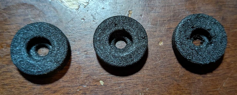
The last thing I did before fully assembling the mouse was to print off some feet so I didn’t drag bolts on the bottom all over my desk. I tried out TPU Air from Siraya Tech that has a varying durometer based off of print temperature and used their default 60A, 65A, and 70A settings. The feet with these settings are shown below left to right; I went with the 65A one since I liked the compression and quality the most.
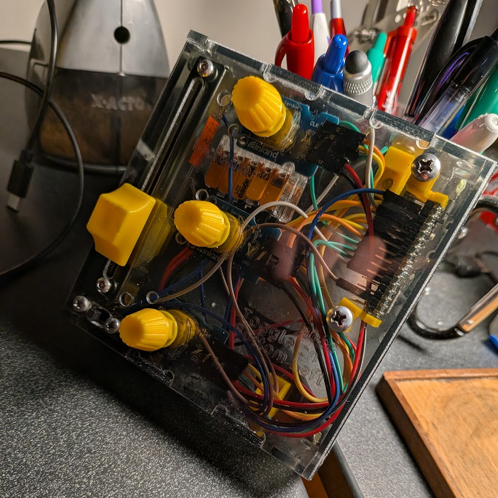
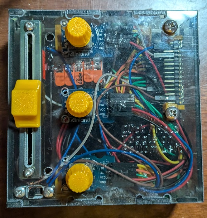
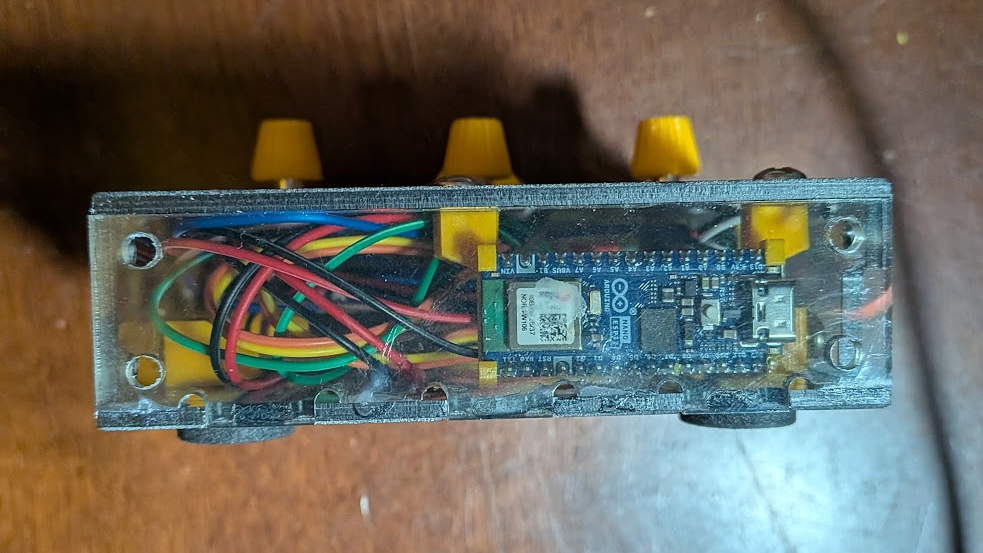
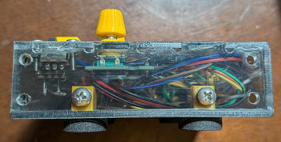
Different Viewpoints of Assembly
What I Learned
I hadn’t done any wiring for a project besides for lights on my dust-shoe and some prototyping for a class project, so I experienced the pitfall of cutting wires too short and not providing enough room for those wires. In the future I’ll definitely try and give more wiggle room for myself and colleagues, and maybe even make routing plans/diagrams for designs – we’ll see (definitely). Similarly, I haven’t done any coding and this project had me practicing the most important skill for starting out, figuring out how to research methods and syntax online.
Link to CAD: EaS Mouse
Link to Final Code: https://johnsonspot.com/etch-a-sketch-mouse-code/