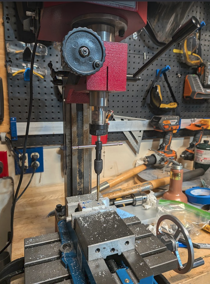
This summer I played around with my dad’s micro-mill, getting more comfortable in using it and making tools to make it easier to use.
Widened Hand-Wheels
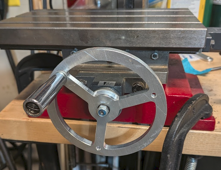
While flattening tube ends for my collapsing shelf I had trouble taking more than 5 thou passes because of the small lever arm on the original hand wheels. I also had a hard time raising the Z-axis, partially due to poor leverage but also because of the small lever arm.
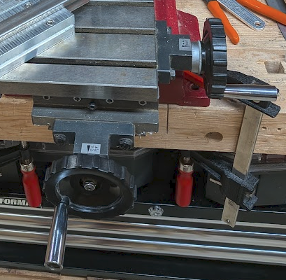
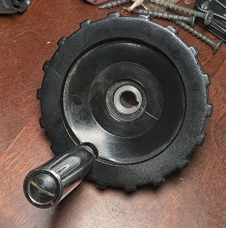
The existing hand-wheels were about 3″ wide, while how I mounted the mill allows for 5″ wheels plus some clearance for my hands. Taking off the wheels allowed me to learn how they interface with the bed axes as well as take the measurements I needed to model a new wheel in CAD.
Before committing to machining multiple 5″ circles out of a limited aluminum supply, I 3d-printed a prototype I could mount to ensure I left my hand enough room to spin the new wheels. The large pockets on the wheel are somewhat for the thrill of removing material with a full cut depth, but also to test how well my hand could fit in the pocket as an alternative to the handle for moving the axis.
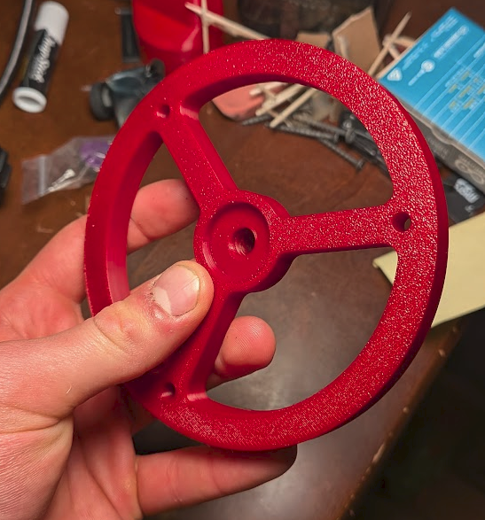
For ease of printing and future machining, I broke the prototype wheel into multiple parts. A thick, keyed hub with a rounded hexagonal profile and thinner octagonal profile presses into the wheel and another part that holds a dial measuring displacement. The original wheels prevent this dial from spinning relative to the wheel unless moved by the user using a spring sitting in a groove, which I lack the ability to replicate in metal without redesigning such a simple solution. So, I added the octagonal profile to slide a 3d-printed collar with the spring-groove. For wear resistance I used the strongest I had available, which I’d implement later when I machined the final wheels.
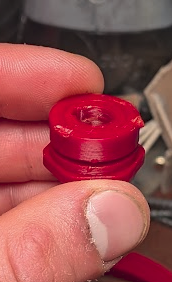
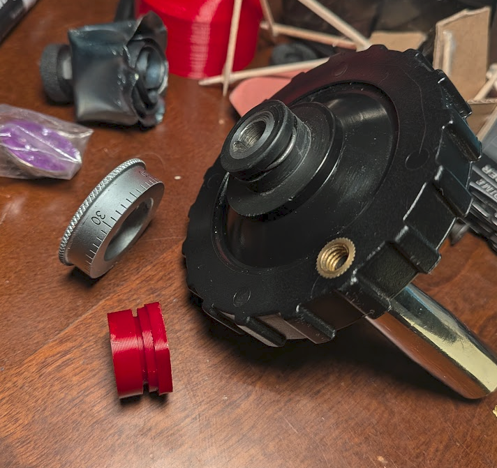
I was mostly satisfied with the prototype wheels, so I started on its metal counterpart after a couple small tweaks. The first components I machined were the hubs using the tape-and-glue method I’ve used many times before. On the hubs for my aluminum robot chassis project, which were a very similar dimension, I had difficulty managing heat during milling and had to keep careful watch over the machine. This time I wanted a safer program, so I tried leaving some material connecting the hubs to the main block of aluminum that I cut off afterwards. While requiring more post processing to separate the hubs and remove the very sharp edges, I was more confident in the program. If I had to make many more of these parts I’d do the same thing over again, although for better tolerancing and processing I’d add material on the bottom of the part and mill it off in a vise.
Returning to the bigger picture, to have these hubs turn the axis lead screws I needed to add a slot. It’s too small to do on the CNC, which means it was small enough to manually file down with precision files and painstakingly check its fit on the shaft.
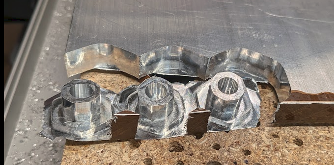
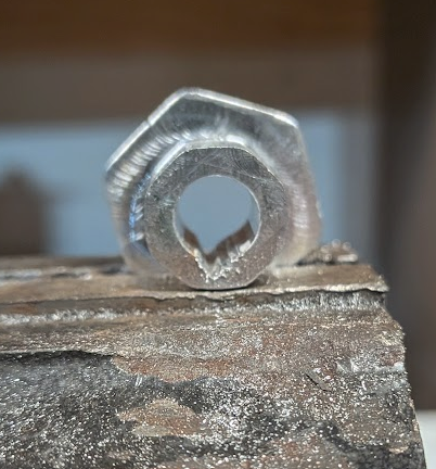
After the hubs, I machined the wheels and tapped a hole for the handle off the original wheels. I need to work on my router tolerances, since the pocket for the hub on the wheels was too small and the hub was oversized. Again I used files and checked fit for each wheel-hub pair, making sure I kept the hub and wheel I checked it on together. I also lost one of the springs from the original wheels, which I used an O-ring to solve. It’s too loose and isn’t a long term solution, but it’s good enough for the short term and for low tolerance parts.
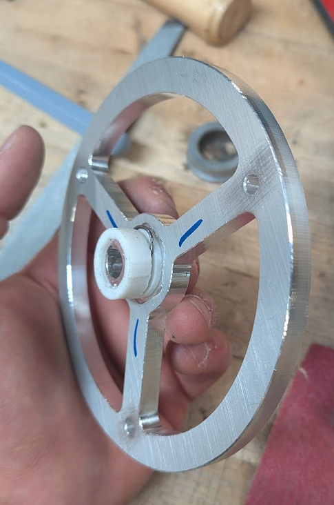
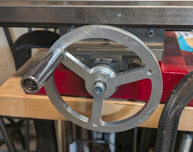
These wheels made machining inserts for my collapsing shelf much easier, allowing a higher step-over than before and thus a faster time machining them. I also learned how the handle of this mill are assembled and have ideas on how to control the axes with a drill or impact to speed up large movements.
Turning
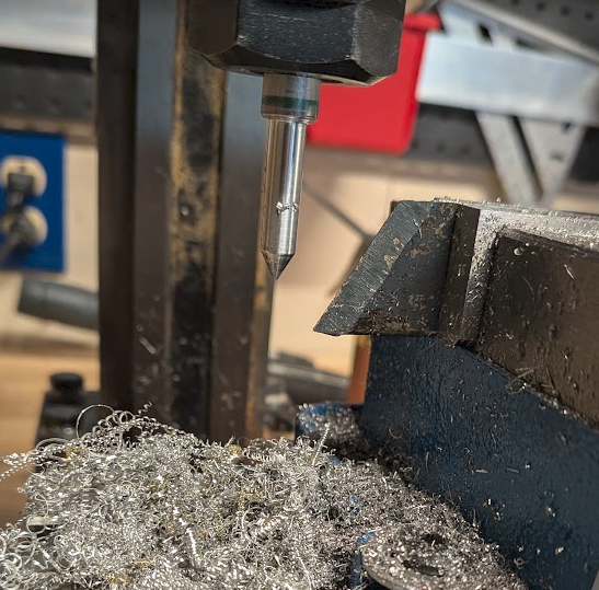
I wanted to try turning on the mill, so I tossed a chunk of aluminum rod into the chuck and a chipped O-flute in the vise horizontally and went to town. That endmill was too flexible and hard to align, which led me to making a new cutting tool out of scrap that solved both problems.
To ensure it was easy to throw in the vise and get turning, I started with a section of scrap steel sheet I rough-cut on the bandsaw. I used a belt sander with a fence to get nice 45 and 60 degree angles on either side, then ground edges on to make cutting easier. Lastly, I blasted the steel with a blowtorch until it glowed red-hot and immediately quenched it to harden it and ideally keep its edge.
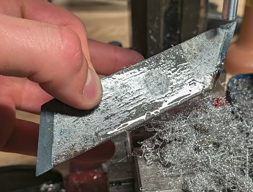
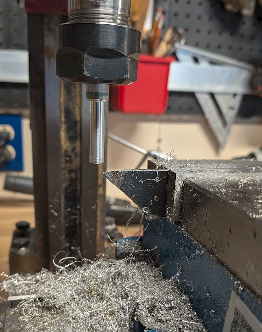
My goal for this tool and turning was to make a tapered pin that presses on the back of a tap in the mill to keep it aligned, which was why I added the 60 degree side to the tool. This wasn’t too difficult, although I had to get a feel for how aggressive I could be using the mill as a lathe.
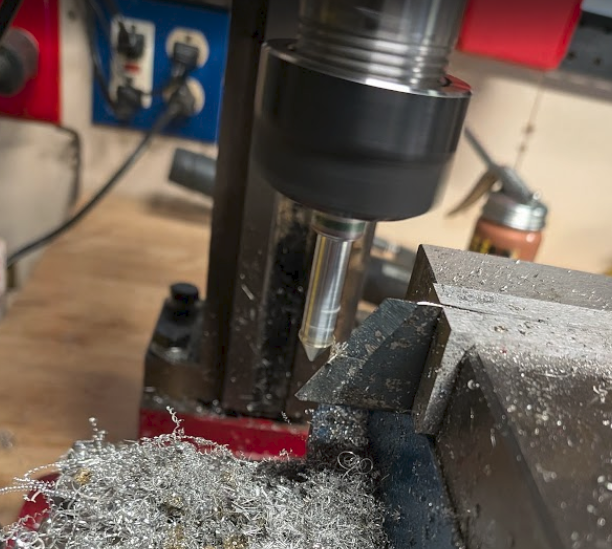
In this mini-project I learned about how much I can push the spindle of the mill and also made a couple custom tools. In the future I’d like to try lathe-style drilling and bore operations, however my setup might not have enough vertical room to try.
Wrenches
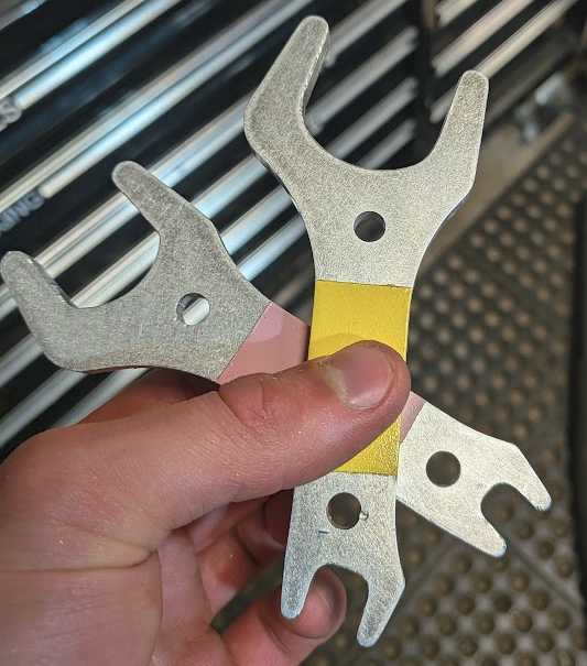
I designed these wrenches to use on the collet and drawbar with the same techniques I’ve used in other wrenches. Not much to say besides that they work fine.
Steel Parallels
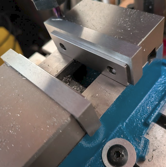
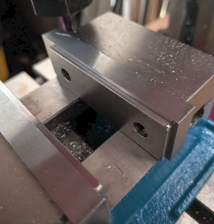
My go-to parallel for this vise was a 3/8″ round bar on its side, but I almost snapped a drill bit on it drilling through a workpiece. I figured something lower-profile would probably be safer and more reliable, so I grabbed some scrap steel and got to work.
In CAD I made simple rectangles with a 750 and 950 thou heights to act as parallels, which gave me either a 1/4″ or 50 thou grip on the workpiece in the vise. I wanted to make these out of steel so that I could hammer on them and not worry too much about deformation, however I hadn’t (intentionally) machined any steels on the CNC router before. This meant I had to determine my feeds and speeds for the material, which I did very carefully on a worn down 2-flute. I used the holes bored into the parallels for hold-down screws as opportunities to test combinations of parameters, then used feedback from milling sound and surface finish (and some sparking) to modify my tool data. When I was satisfied with the quality of cut, I saved the tool in Fusion and ran contour paths to cut out the parallel. For maximum degrees of flatness and parallelism I ran a small stepover and repeated finishing passes at the final cut depth. In the end I got within .005″ of parallel and the nominal dimension, which is good enough for me and better than I got with my handwheels on an easier material.
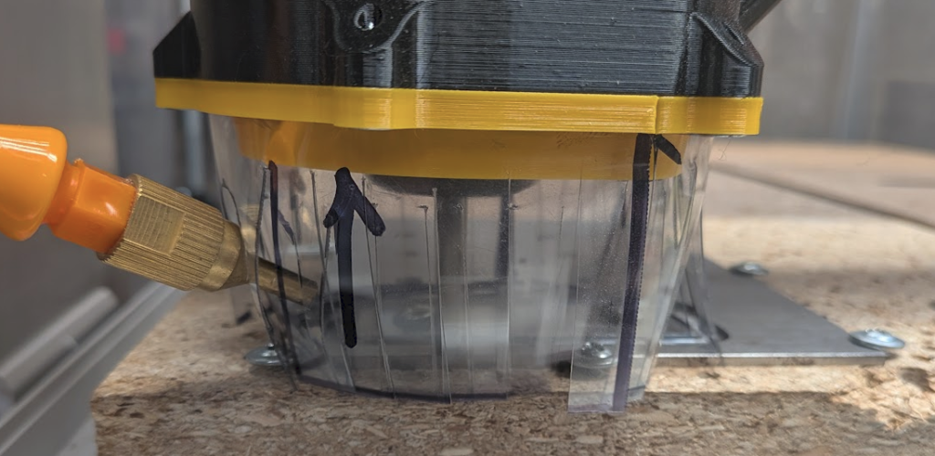
These parallels for how little I’ve gotten to use them have been handy, and they also gave me an excuse to play around with steel on the CNC. Earlier in the summer I made a special dust shoe that doesn’t use any magnets in the hope I could use it, so I’m glad it didn’t go to waste. If I machine more steel I won’t be able to reuse my cutting data since I don’t know the grade or any relevant material information for, but having to play around and experiment with cutting variables is never dull.