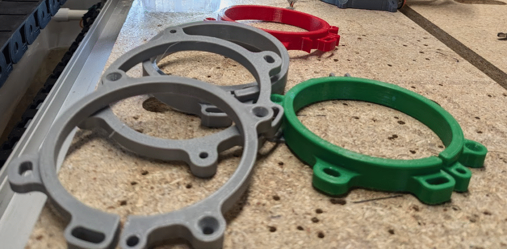
My previous Dust Collection Update worked pretty well, but it had some issues and could’ve been better. This time I tried to make it more effective and user friendly with some big reworks.
Problems and Iteration with the V6
One of the biggest problems I had with the V6 was it’s cover, which required the spindle be raised past a certain height to be removed. This forced me to go back and forth between the controller and machine in situations I wanted to get to my tool, often when I ran into an urgent or distressing problem. The magnets that held it on in the back and served as power terminals for the cover spotlight also gave me issues, inaccessible when wires came loose or the connection broke.
Another issue was that I didn’t like the vacuum hose adapter. It worked okay, but I felt that the opening wasn’t big enough and that loose cutoffs could too-easily get suck right next to the tool in use.
Initial Design of the V7
I ended up scrapping my first model of the redesign but still got some benefit from it, serving as a first iteration of new features. The most obvious change is it’s elongated side, which I took inspiration for from other CNC router dust collections with their hose off to the side. My thinking was that anything stuck on the vacuum would be pretty clear of the spindle, hopefully solving my concern with cutoffs and as a byproduct make it easier for chips to get sucked up. This made it look quite silly and rather bulky, dooming the design when I used a 3D assembly of an OMIO router to verify that it fit — it didn’t. The machine the shoe is attached to is within an enclosure with a bit of clearance on either side, which the shoe would be pretty far up against at the maximum X position. Since I’d rather not squash the vacuum hose, I decided to throw away the design even though I was ready to start printing it out.
Another significant change with this design is the way that the cover comes off. Rather than wrap 2/3’s around around the spindle, I made the cover only wrap halfway around and interface with the cover via flat sides. Now it could slide off, but with the tradeoff of less room to work with around the Z-axis.
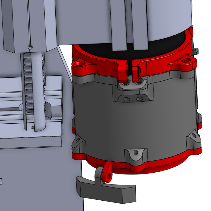
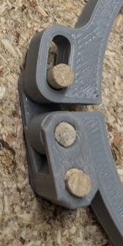
There were only a couple features where I needed a lower profile, which were attaching the brush mount and holding the cover. For the former, I planned on insetting a countersunk hole right at the edges of the cover and body into where the brush is press-fit. This would add a gap in one of the brush layers, but eliminate the potential for a gap between bolted parts within my constraints. As for how the cover would be held, I reoriented the magnets pushed up against each other and used larger, lower profile ones inset into matched pairs of tabs and pockets. As a precaution against magnets being pulled out of their press-fit pockets as before, I placed a backing in between each pair that separated the magnets and aligned the force from the magnet with the direction needed to keep the magnet seated correctly. The consequence of these magnets not touching was that I couldn’t pass an electrical connection through them, but that would have made the intentionally compact tabs too bulky; instead, I added another pair of magnets where the cover is held from the top and planned wire routing through there.
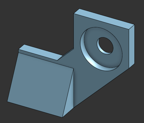
One last feature that I added was a replaceable spotlight mount, which was also one of my last tweaks to the V6. I’d originally designed integrated mounts onto the cover and body of that model to reduce the number of parts needed to be printed, but when one of those broke I had to reprint the second largest part of the model. Of course, I took the opportunity to try something new and made a small, modular mount; the goal was to have something that could easily break as easily swappable as possible, which I tried to apply on this new design.
Final Design of the V7
After throwing away a model I’d spent days on, I went back to the drawing board and refined some of the concepts in it. My next iteration had a couple major changes, maintaining much of cover’s design but reworking the main body.
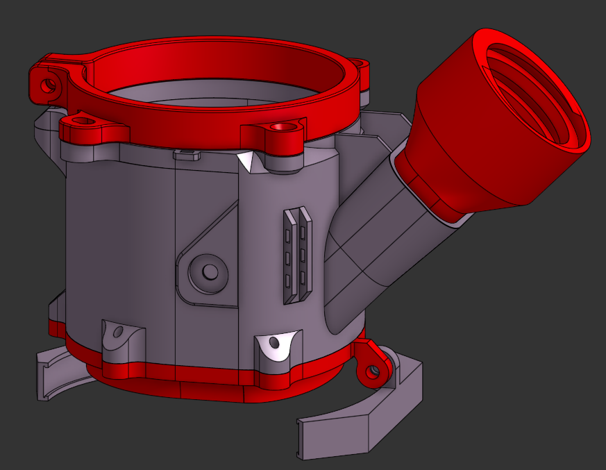
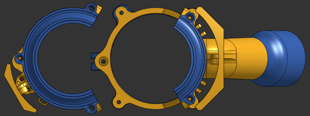
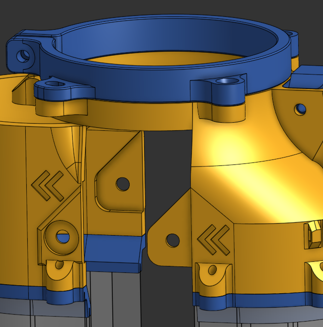
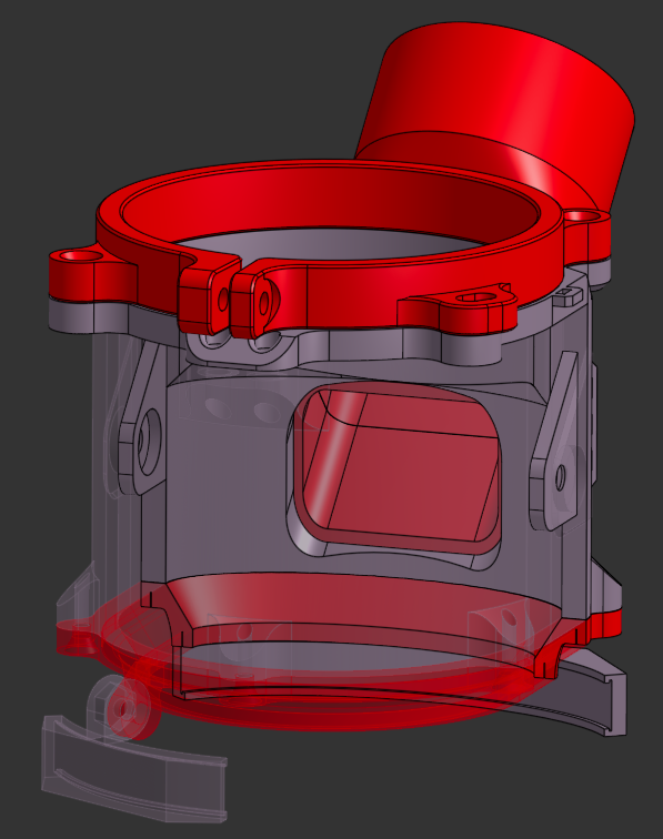
I really liked the design I had for the cover sliding off to the side, leading me to keep the same system of low profile tabs and a electrical connection relocated to an easier-to-reach spot. Some prototypes printed in the same orientation as the magnet pockets helped flesh out press-fitting dimensions, as well as verify that the magnets would have enough holding power even with a decent amount of plastic in between them. Because of the way I 3D-print the body and cover, I had to either have supports or add a slop to the tabs. It wasn’t any extra trouble to add one, and also had the benefit of allowing the cover to be taken off either directly to the side or down at a 45 degree angle.
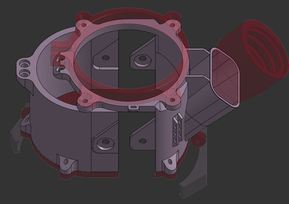
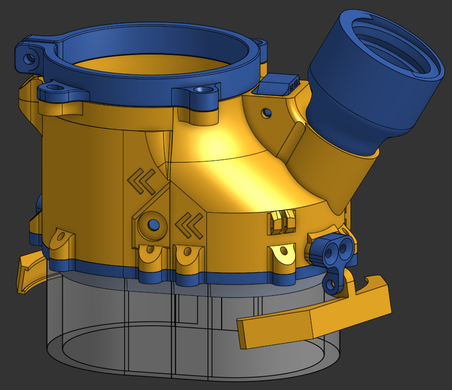
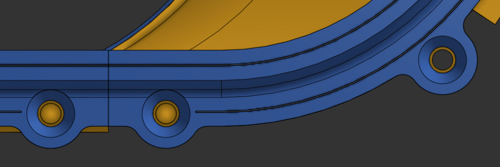
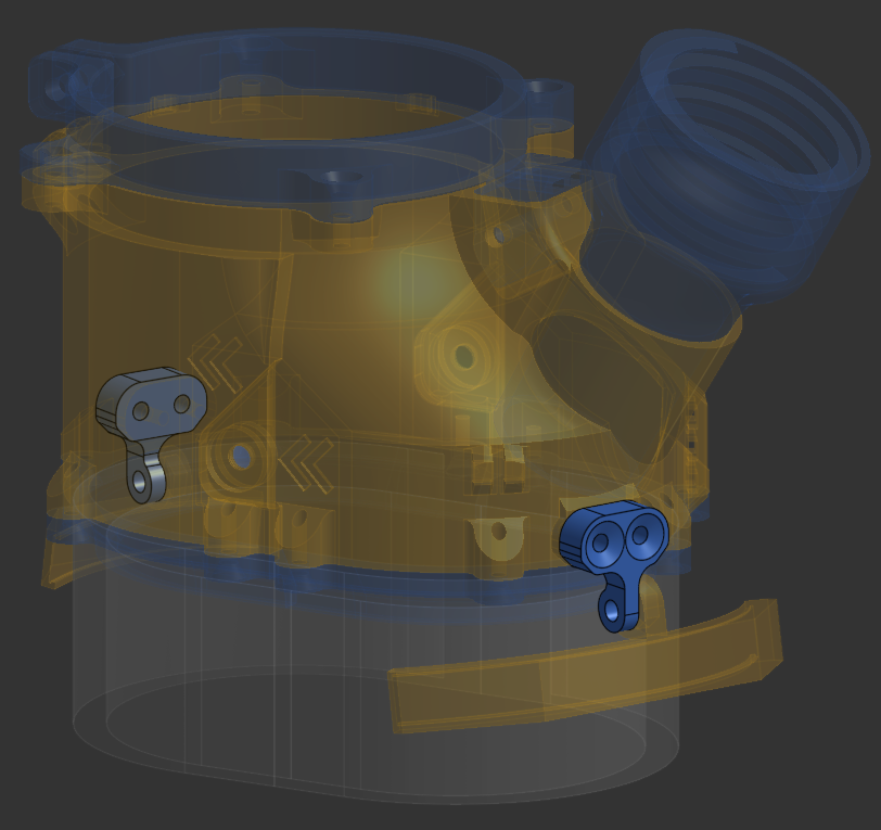
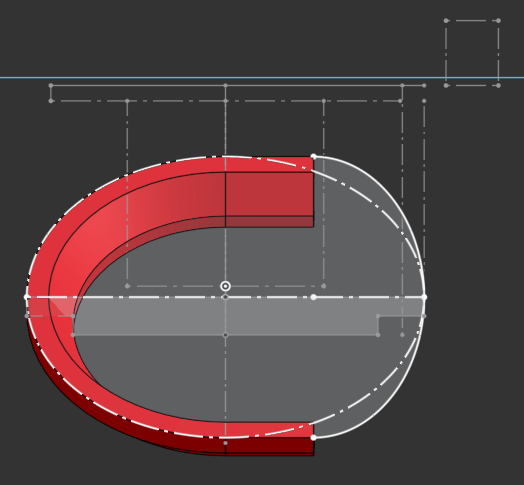
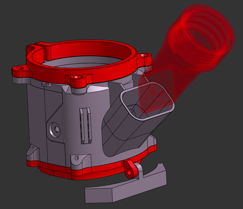
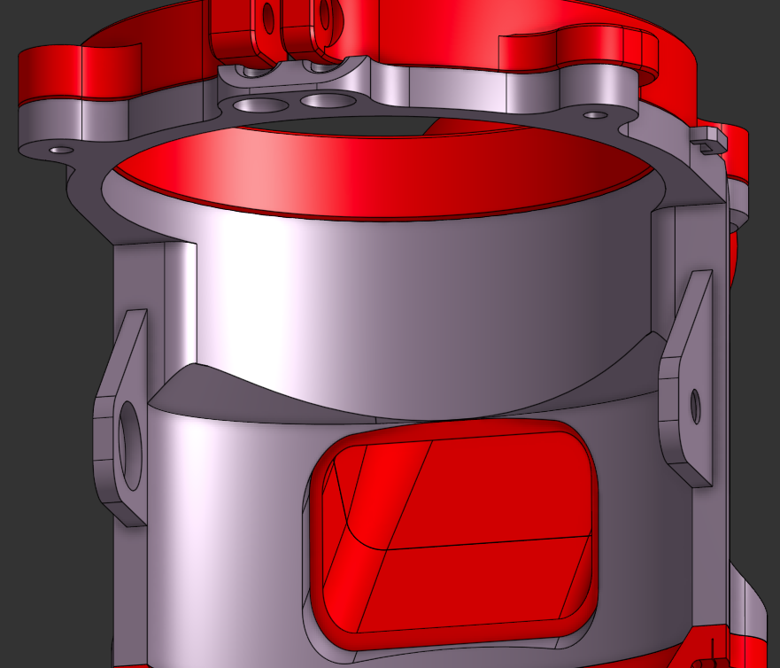
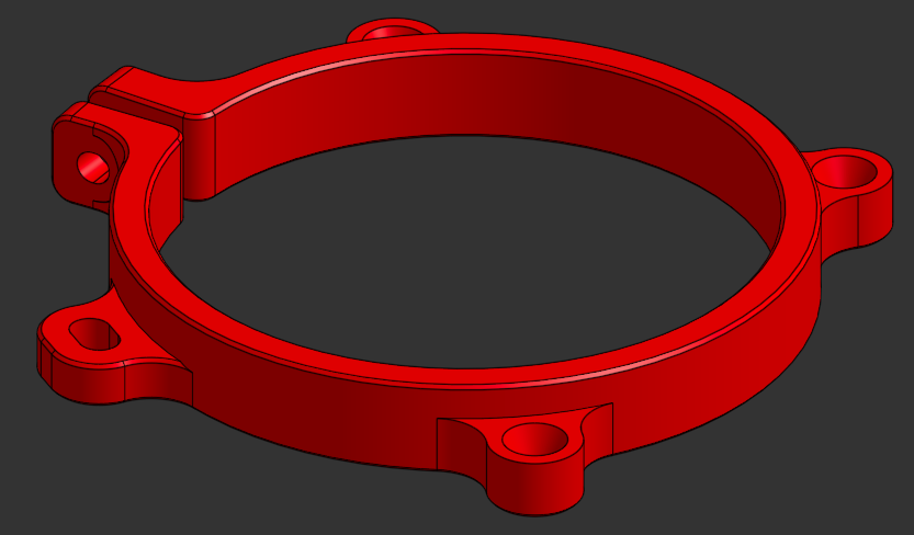
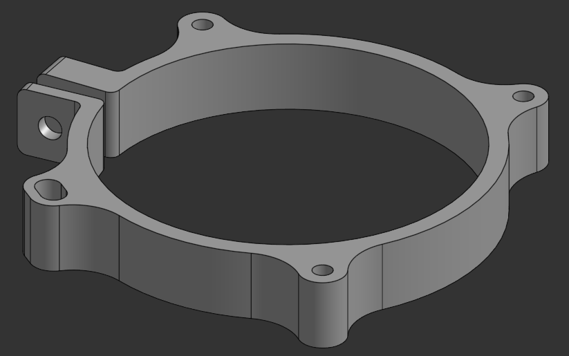
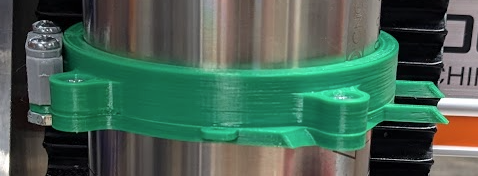
To avoid extending the body to add these tabs and making the shoe too bulky, I used an elliptical arc to be tangent to the flats of the cover while maintaining the same overall width as the V6. This took some effort to connect up to the circular profile of the spindle mount, but was compact enough to be worth it. To also maintain the tight constraints on the back yet be simpler than previously, I removed a set of screws from the brush mount so that the outer brush layer wouldn’t have a gap making it less effective.
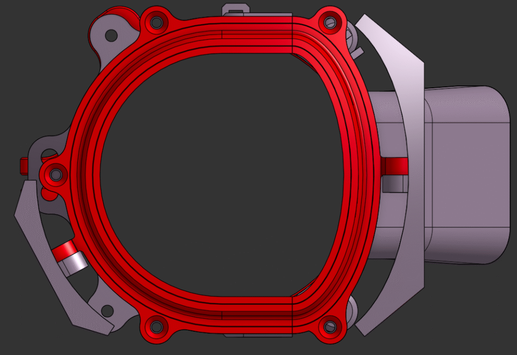
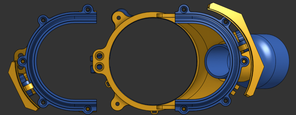
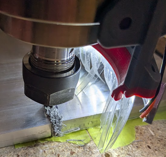
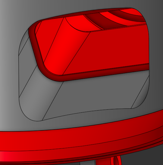
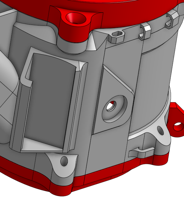
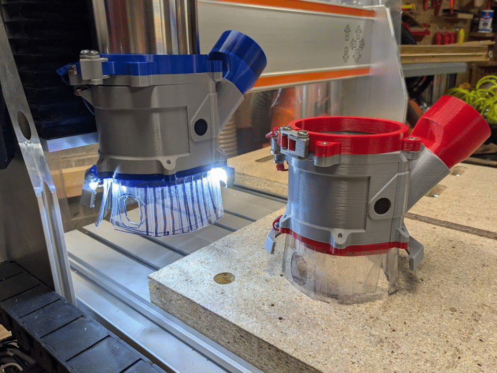
Besides for the geometry needed for a side-sliding cover, the other big change I made was to replace a circular vacuum adapter for a wider rectangular one. I don’t know the physics and fluid dynamics yet to determine if this actually increases suction power, but the wide hose and conveniently wide body make it easier to suck up large cutoffs or globs of chips. The new bottom profile of the hole also provides a more direct path for many chips to the vacuum, which should mean it is more effective even if actual suction power doesn’t change. Oh, and the flat edge on the rectangle compared to a circle makes it better at clearing chips from the flat wasteboard.
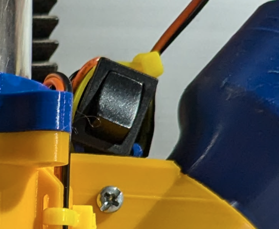
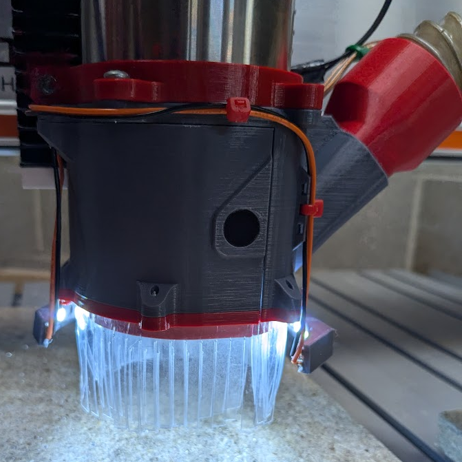
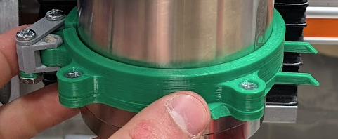
Another change was to attach the spotlights to the brush mounts. I’d done this initially, back when I was prototyping them on the V5, and probably shouldn’t have moved them. The brush mounts are meant to be replaceable anyway – one reason why I originally made them separate from the body – and eliminate the added complexity, parts, and bulk of other solutions. Simplifying the lights further, I didn’t add any mounting for a light switch since being on the dust shoe that moves in the X, Y, and Z axis makes it hard and even dangerous to try use.
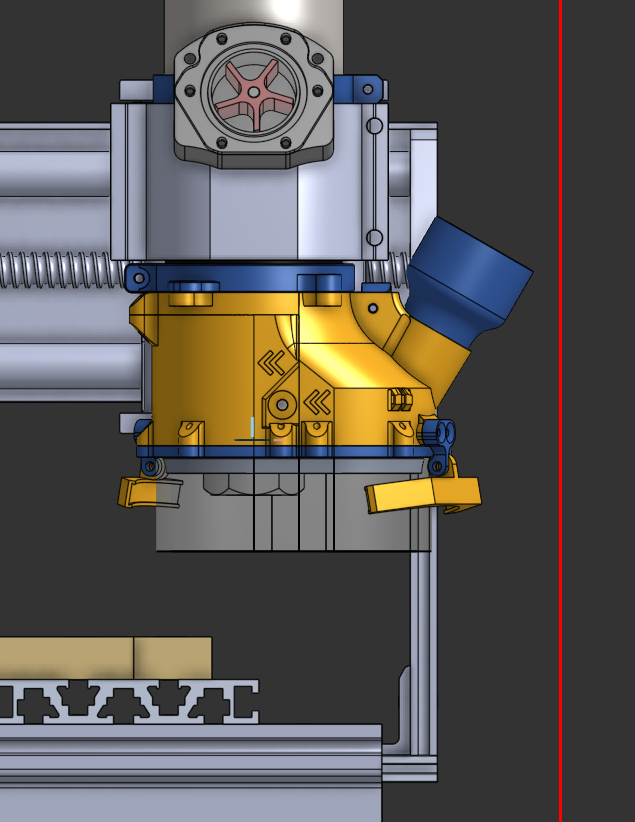
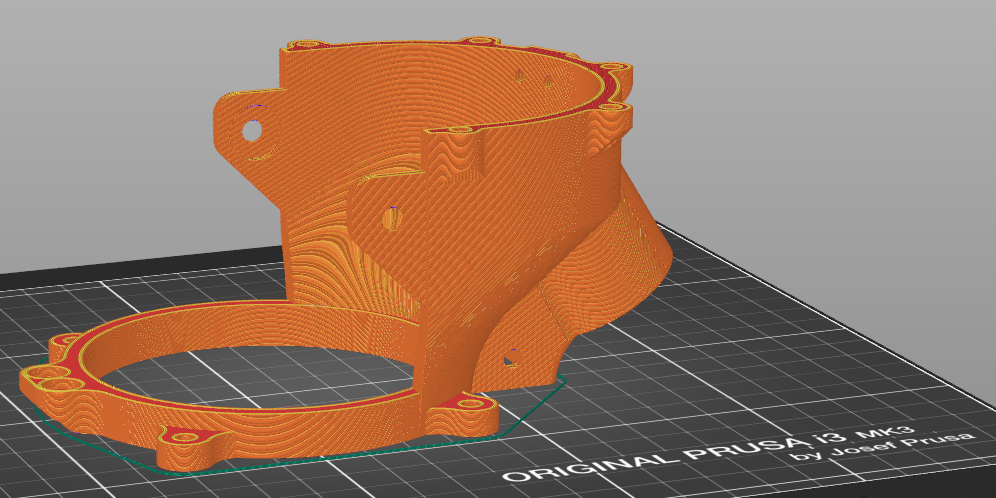
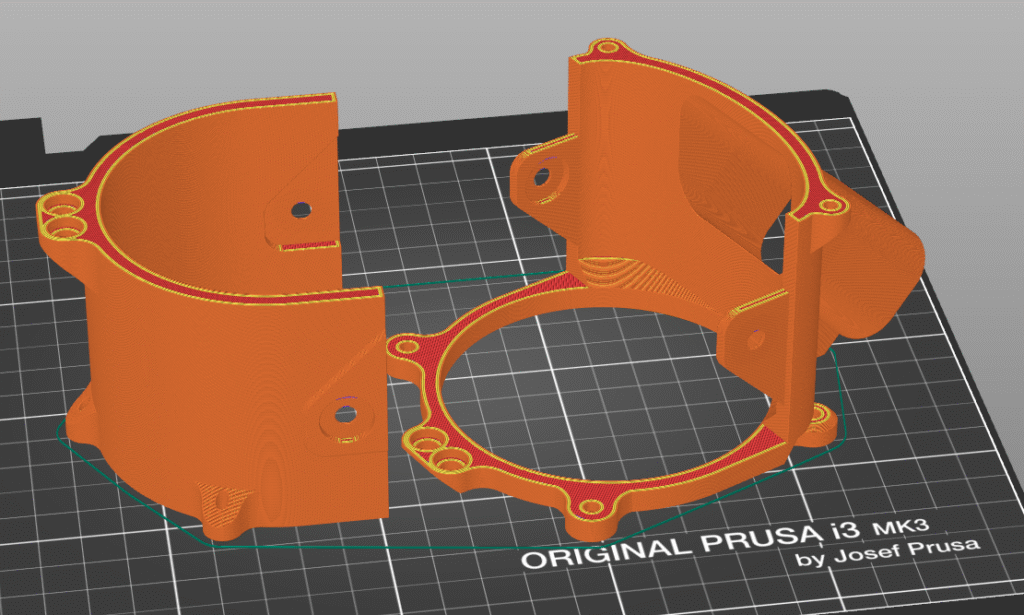
As I made these design decisions, I made sure to think about how well my parts would print. This took the form of sloped overhangs and ribs, which let me print without any supports where previous versions needed a little help. I also tried to think about how the assembly would interact with the system it’d mount to, using the router model and construction geometry such as a plane representing the Z-axis in relation to the spindle to ensure everything would work okay.
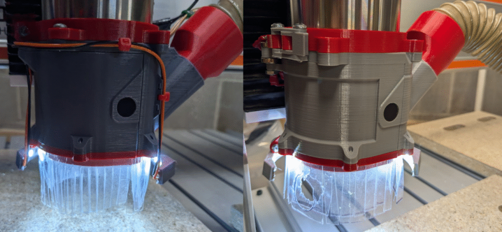
Problems with the V7
I got a couple months use out of this version, finding that the big changes were pretty effective and made the shoe more user friendly. Even though this new model could have the cover removed when the spindle was down and potentially stuck, I found some quirks and possible areas of improvement.
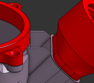
One of the first annoyances I found was that chips would accumulate in pockets where differing geometry came together, like in front of an originally flat vacuum adapter and where I made the elliptical body became abruptly a circle. This wasn’t a big problem, but it left some messes when the debris shook loose so I extended some profiles in CAD to remove these areas.
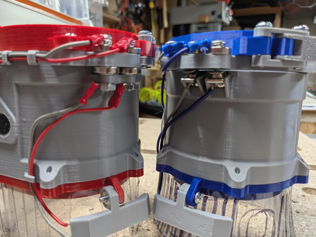
Another issue was with the wiring. The contact between the magnets and their respective wires jammed into press-fits wasn’t too effective on the V6, and I made it less so by forcing the wires to do a sharp turn immediately outside their pocket. This made it both very easy for the wires to pull loose and frankly rather ugly in its crudeness.
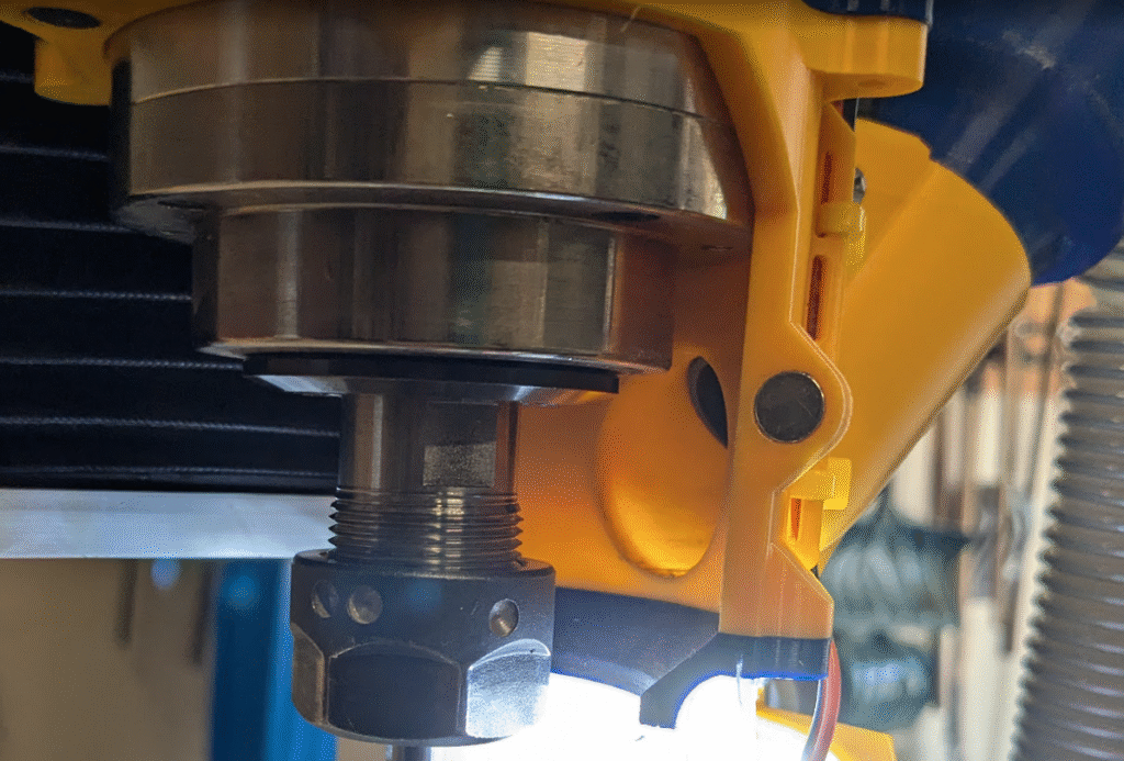
Lastly, the mount attached to the spindle started to give me problems. The nut and bolt I used to squeeze the spindle were getting stripped from the weirdly angled forces involved, and on top of that I was getting fed up with needing a tool to adjust the dust shoe’s height. My previous iterations on the mount had largely focused strengthening and polishing it, with little actual thought to make it work better since the V4 prototype.
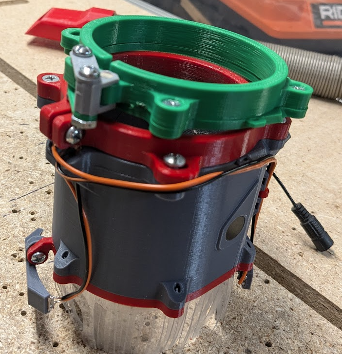
Designing the V7.1

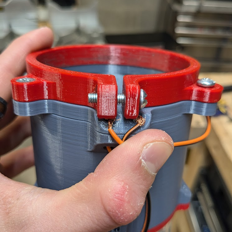
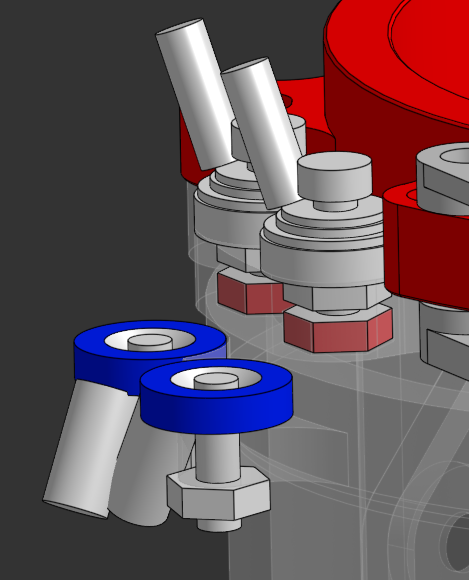
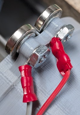
There were three main goals of this redesign: easy height adjustment, a more reliable electrical connection between the cover and body, and better managed wiring. To start, I sketched out some ideas as they came to me over a couple days to detail what the elements of couplers and adjusters would be. One such element of a coupler had to be a magnet, so that it could serve as an anchor for the cover, and also that the wire had to be bolted down rather than jammed in. my first thought of how to accomplish this would be drilling a hole in a magnet, then putting a bolt through a wire wrapped into a loop though with a nut acting as the contact; my dad pointed me towards ring connectors and some countersunk magnets he had, and I made some prototypes to determine what hardware was essential and what geometry I needed to mount it.
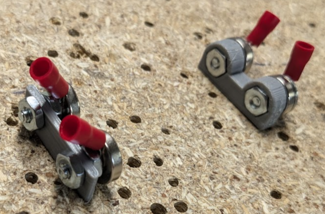
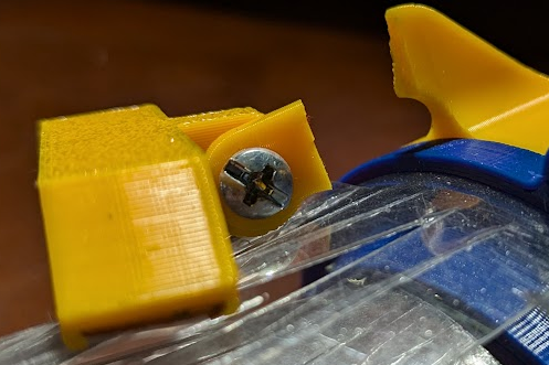
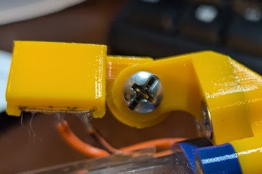
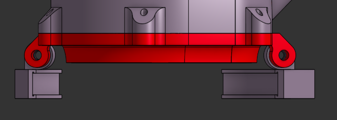
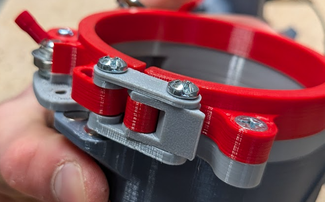
Simultaneously, I worked on designing a latch to apply tension onto the spindle. I based my model on toggle latches that I saw around me, printing prototypes to achieve the right amount of grip in both the engaged and free position. Early versions of my tests were intentionally bare-bones to focus on how the latch would work, and from there I added more and more details of the final product to simulate how the latch would work in conjunction with other geometry like mounting hardware
The most influential interaction that the spindle mount had was with the body of the dust shoe, as screws between them limit how much the mount can flex. I’d partially accounted for this in earlier versions of the dust shoe by having one of the connection points be a slot rather than a fixed, countersunk circle and applied the same geometry in a different location to maintain the same effect of increasing how much of the the mount could flex. Tying everything together, I printed a small slice of the body to attach my prototypes and incorporate the constrained flexing into my tests. Once I was satisfied with the clamping power while mounted, I could then finalize the part.
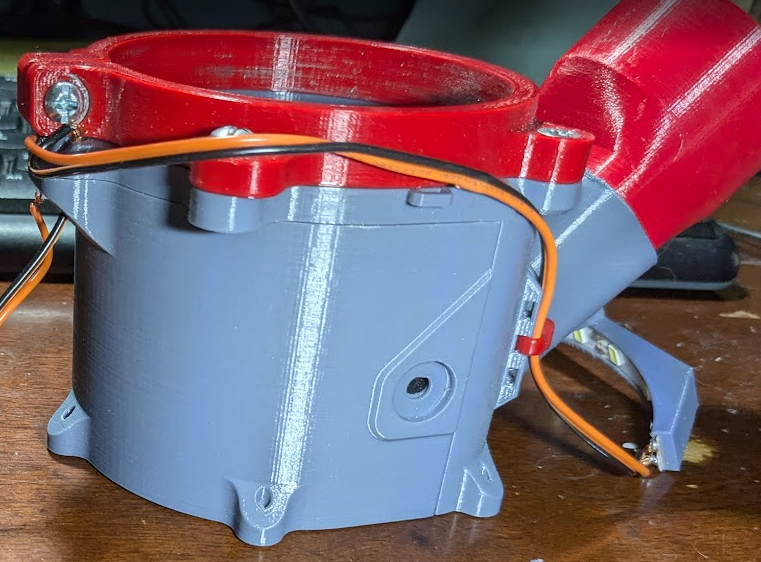
Incorporating the latch into the model in a convenient location did force me to move the electrical contact between the cover and body more out of reach, but testing had show that it was reliable enough for the tradeoff to be worth it. This also made wire routing easier to hide behind the shoe, contributing to the aesthetics of the design.
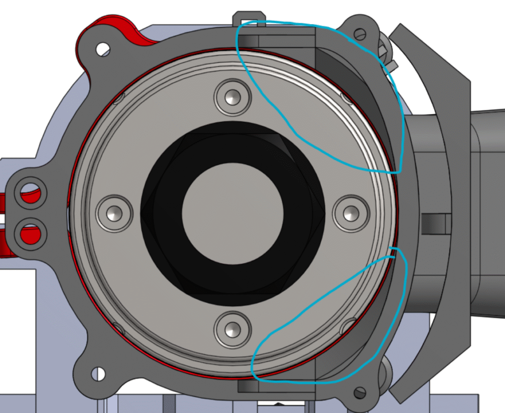
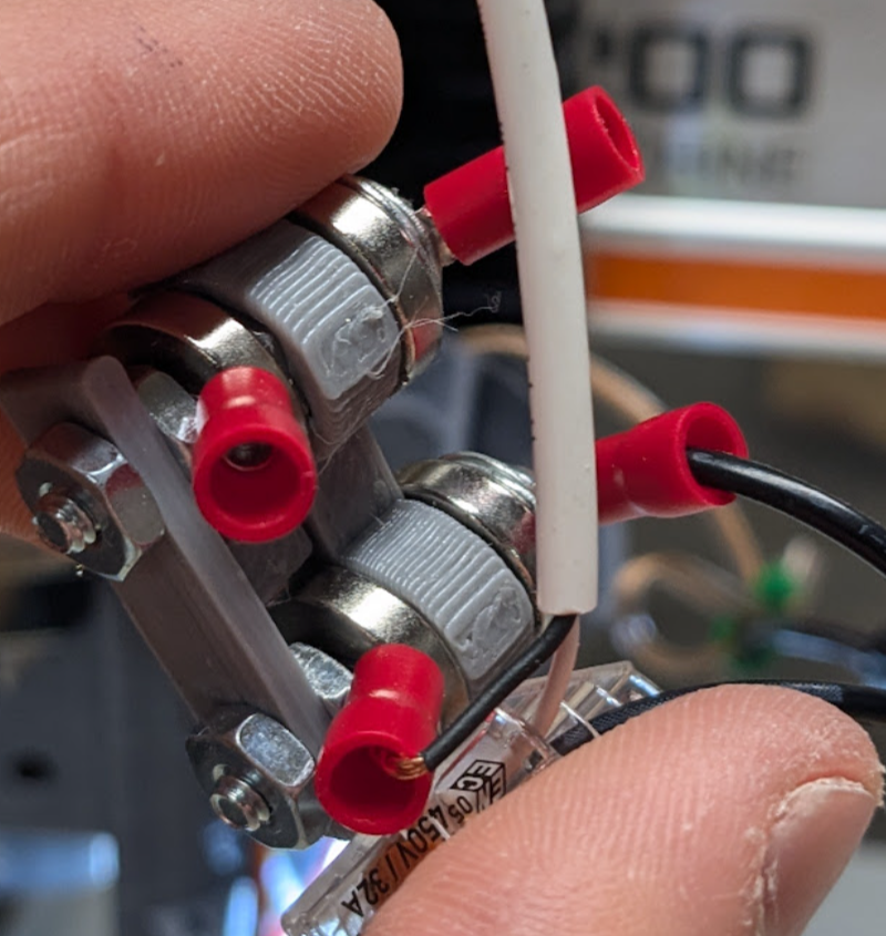
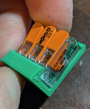
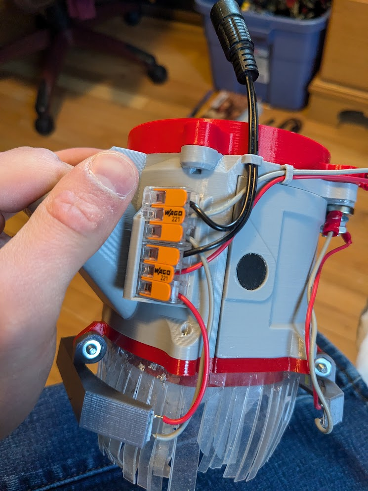
Once I finalized all of the changes to working geometry, I started planning the paths and connections of wiring. To make this part of the project way easier, I planned on using WAGO connectors to both split the incoming power between the body and cover; the choice to use them also made installing and replacing wires easier, allowing it to be reliable held in rather than be soldered or jammed into haphazard connections. Placing the WAGO connectors on the shoe wasn’t too difficult, as all of the electrical components are on the back of the shoe around unused space. Additionally, I’d found an existing model of a clip that I could easily incorporate into my design. Before I spent the time of doing so, however, I drew the paths of my wires on a screenshot of the dust shoe to help visualize my ideas and act as a sanity check that everything would fit.
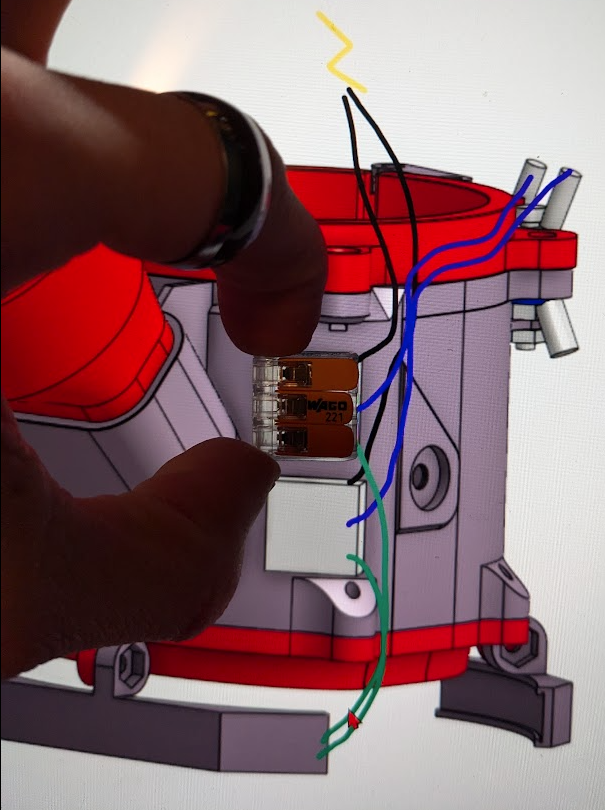
From there, I added the clip geometry as well as some clips and loops to force each wire to take its assigned path. Not all the elements of my wire routing were included with my first prints, being slowly modeled in as I learned more about what I needed through use of the system.
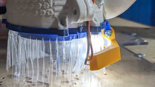
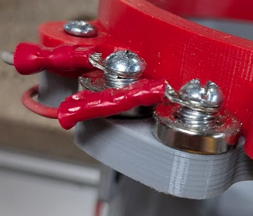
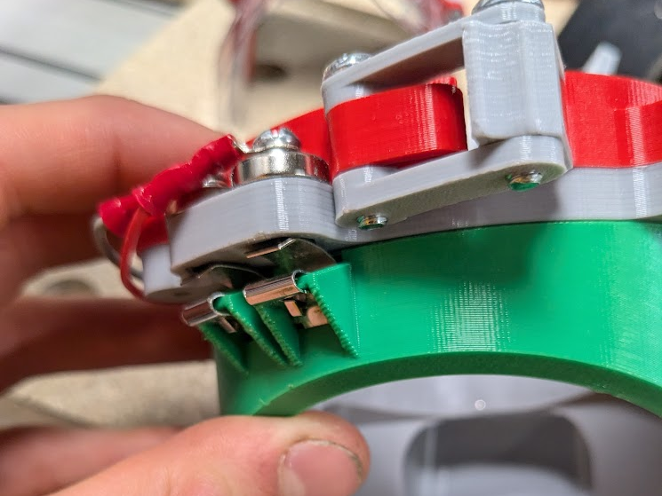
My original plan for the couplers relied on creating a connection between fixed nuts and magnets, which I’d prototyped and worked out dimensions to do while being as flush with the dust shoe as possible. Simplifying further, I also reduced the amount of hardware I used but ended up with a similar problem as before where my cover light kept flashing. An improvement I made after some use was to include a spring on the body’s magnets, which I can tighten or loosen to change how much the connection pushes against the cover’s magnets in order to maintain a solid power transfer with a minimal gap between the two parts of the dust shoe.
Finding a Good Process to Fabricate Brushes
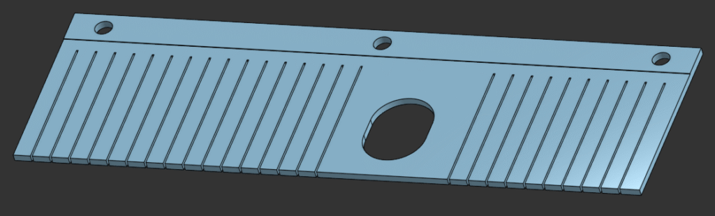
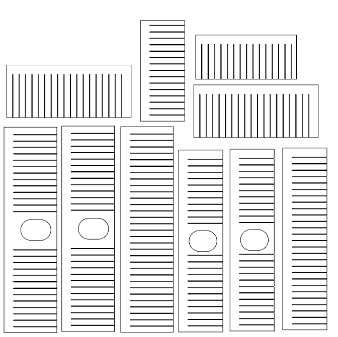
Making brushes to replace damaged ones or add improvements has consistently been a pain in the ass, taking a good amount of effort and time. Measuring, marking, and cutting them by hand when I made my first iteration took forever, and 3D-printed jigs to guide a knife were hard to keep aligned. On the V6 I did some iteration where I added a ledge and holes, allowing a pair of identical jigs to clamp down on a piece of plastic. Still, knives got stuck in the jig and each of four unique brushes needed a pair of them worth an hour of print time. Too annoying.
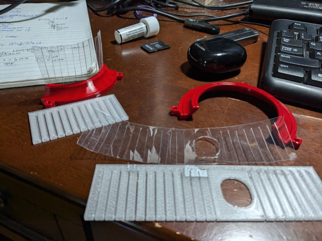
When I redesigned the shoe to need different length brushes, I didn’t want to take a ton of time to remake jigs. For a prototype, I asked my mom if a Cricut machine she uses for vinyl and other materials could cut harder face shield plastic. After crashes and multiple passes that still didn’t cut all the way through, I gave up on that avenue although still used the markings the automated cutting machine made.
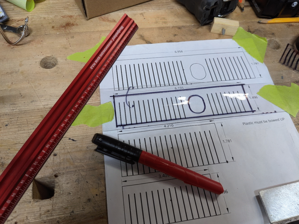
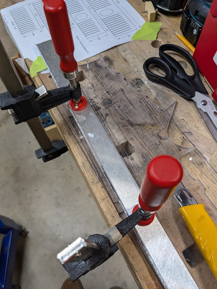
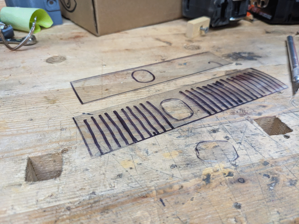
Next I tried using the CNC router with a drag-bit, using various workholding techniques to hold the plastic under tension over various materials. No matter what, the tool couldn’t cut all the way through and left me using a knife and scissors. The bit left indents on whatever material was under the plastic, which I also tried using as grooves to align a knife; didn’t work. The latest thing I’ve done is just printing out the outlines of each brush on some paper, tracing it, then using a clamping/straightedge setup to cut the brush as accurately to size as I can. I don’t bother doing this with all the little slots, which I just cut with scissors once I put the plastic blanks into the brush mounts. It’s a crude solution, but the best tradeoff between quality and time I’ve found so far.
Current State of the Project
I’ve done some minor tweaks, like prototyping a new electrical contact for the cover and altering some geometry, as well as assembling a new dust shoe for the robotics team’s router – my dad got the same model, which the V7 was originally made for. I’m going out of state for college very soon, so this might be my last update to this project. It’s taught me a lot, but is back on hold for now.
Link to CAD – V7 / V7.1 / Slightly upgraded V7.1