Last summer, a volunteer for robotics asked if I could make a replacement part for a bike fender. A hanger he had in house house broke, so I prototyped and machined some parts to help him out again.
Problems and Prototypes
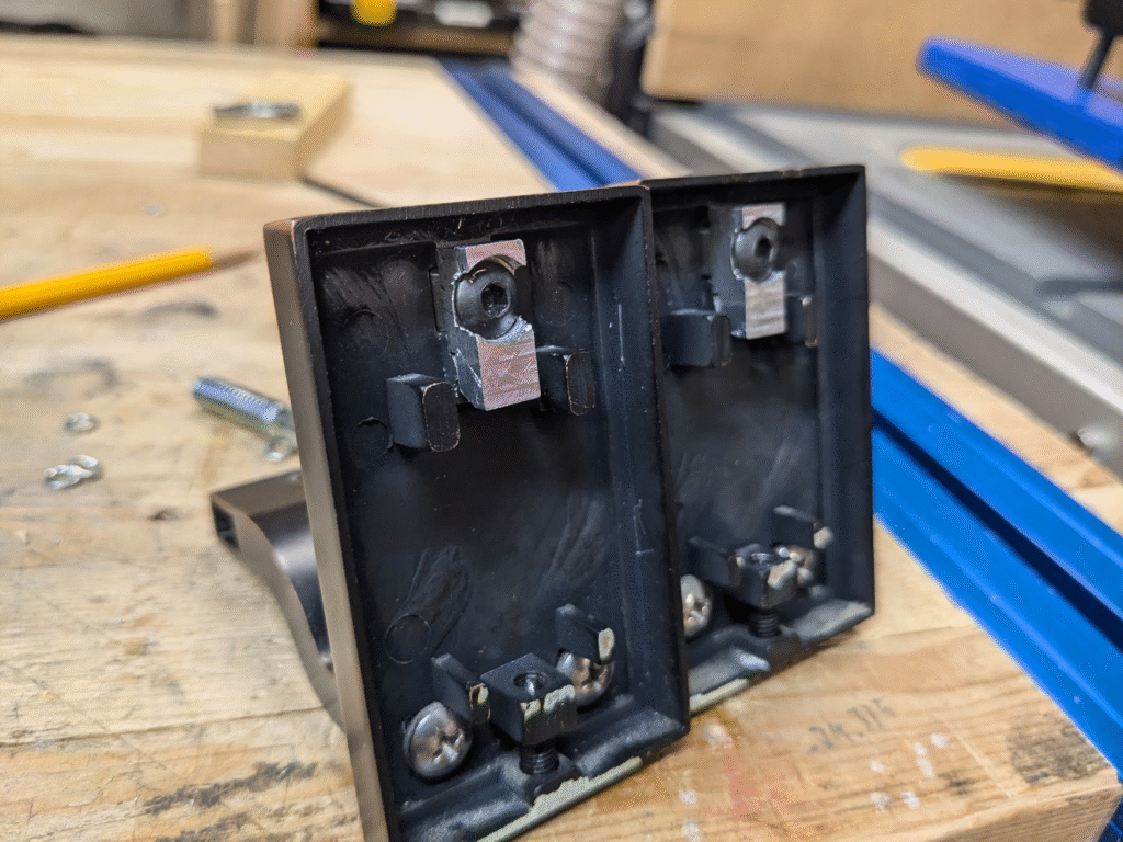
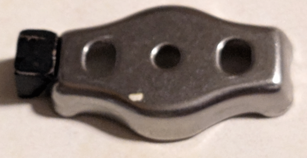
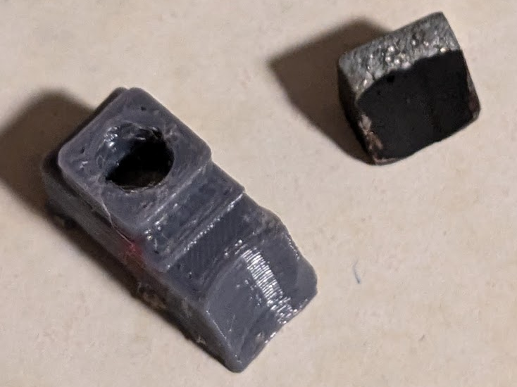
Normally his hanger mounts to two metal anchors screwed to a wall. The broken part, a small metal hook, uses a draft and radius to catch on these anchors and hold it while a lead screw gets driven onto the other side. Due to the location of a bolt to keep the rest of the hanger together this hook has a very thin base, which allowed it to shear and made the hanger unusable.
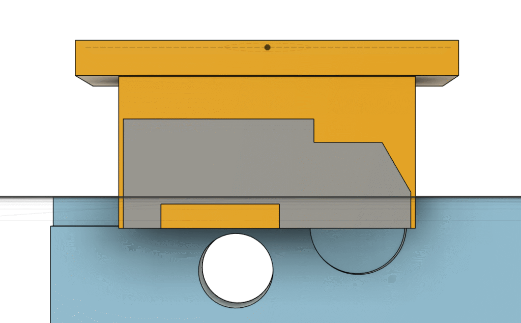
With an understanding of how the hanger mounts and what went wrong, I started measuring and mapping out what I had to work with in a CAD cross section including the ridge leftover from the shear. The bolt mentioned earlier screws into a shallow tapped hole, which I planned on using to mount a replacement for the hook. As I planned out my fix, I had to keep in mind that the hanger needed to sit flush against the wall and thus whatever I did, it had to fit within the walls of the base.
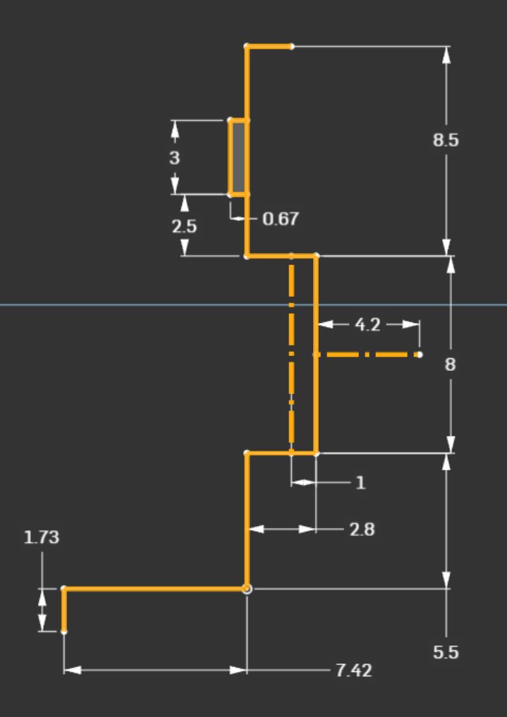
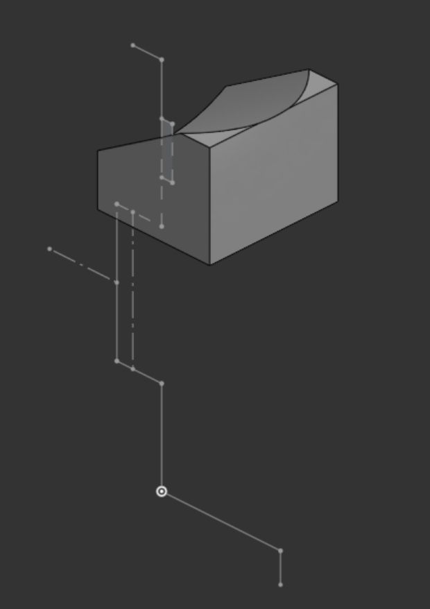
Next I took some measurements of the hook and modeled it, which I had to determine the draft angle and radius on the draft to do. This model was the important, functional part of the hanger which I built off of to create my replacement part. This took the form of extending it to be over the tapped hole, clearing the shear, and fitting the contours of the base in addition to leaving a pocket for a bolthead to keep the hanger flush to walls.
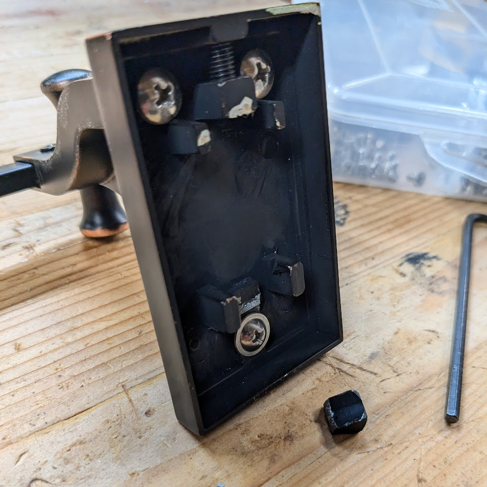
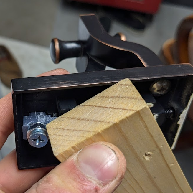
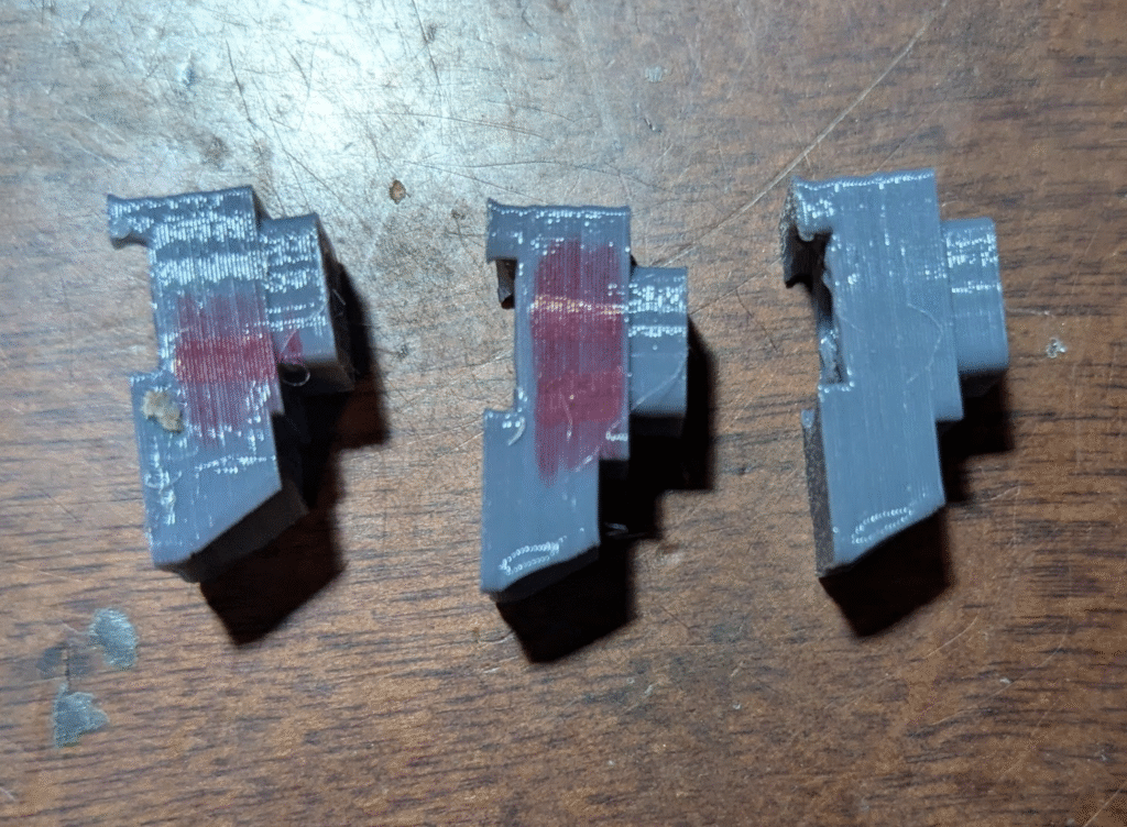
Having a digital model let me start 3D-printing some prototypes. Plastic was okay for prototyping even with some deformation, but I planned on making the final version out of aluminum once I got my tolerances and fit right. To test changes I made, I mounted one of the anchors to a block of wood in a way that would allow me to use a longer bolt before I had a more reasonably sized one. Using this bolt and not one the final version would have came back to bite me later, but was able to make improvements to prevent the part from getting cantilevered out of spec as well as avoiding the remnant from the shear.
Machining the Final Part
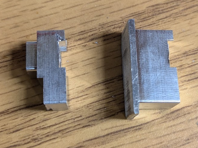
I was very excited to machine two of the final part. For starters, it’s so small that the only viable way I could manufacture it was with one of my vises I love to use. Additionally, I got to try out a new industry-standard fixture method where I machine custom jaws to hold the parts in a fixed location and orientation.
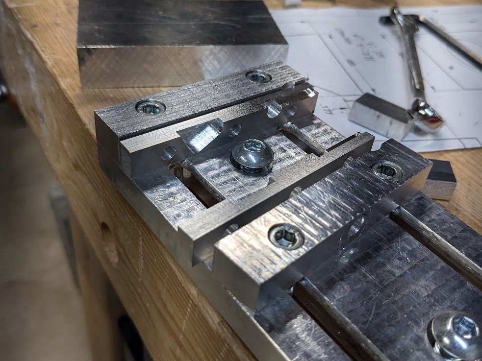
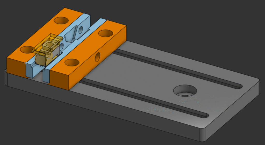
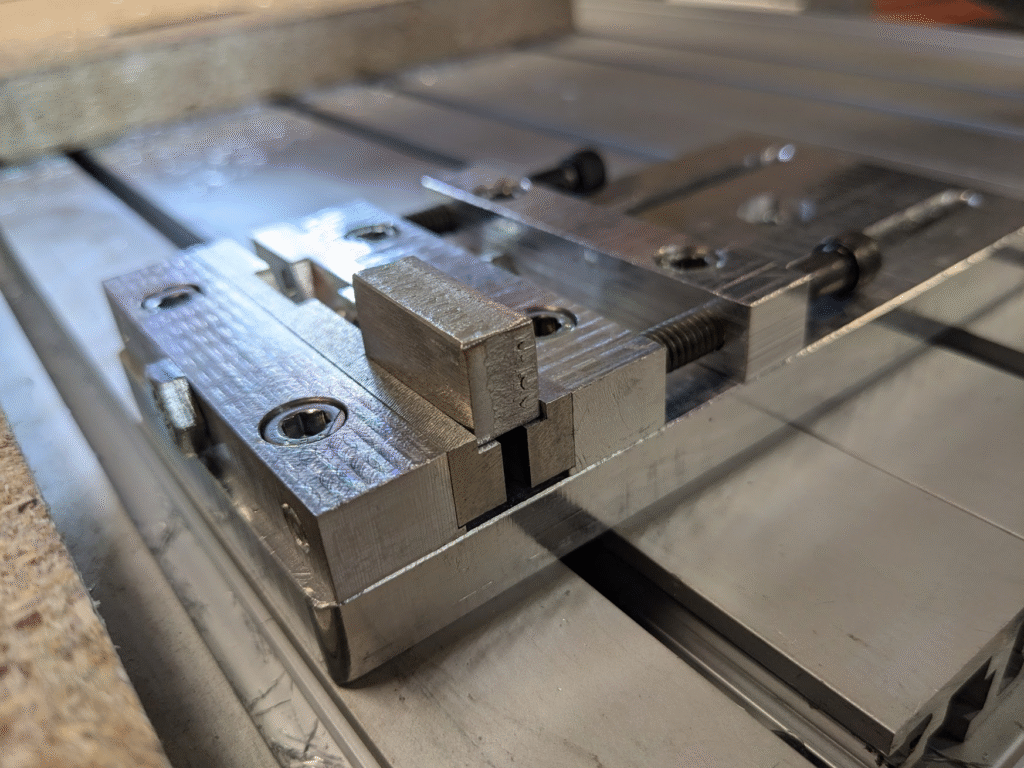
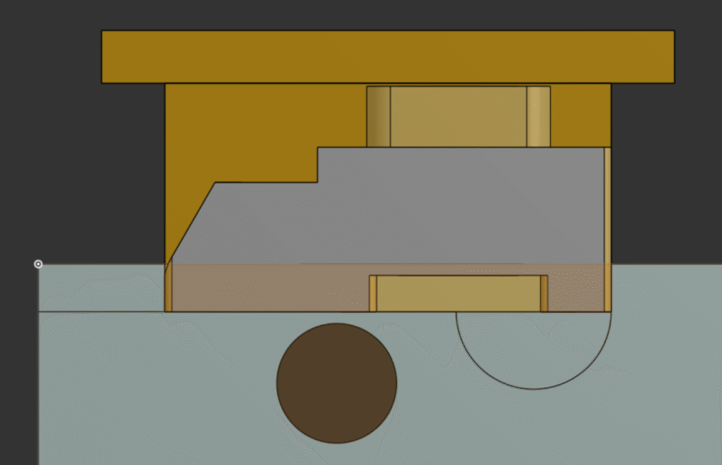
My first step was to get my vise ready, which I’d already started for another project by putting mounting holes on each mounted jaw. I machined the custom removable jaws out of some 1/4″ stock, tapped them, than manually fed G-code into the machine to add a 50 thou slot onto the side of the mounted jaws to force the custom jaws to be aligned correctly. This left me with as accurate of a zero as I could get with my machine’s setup, as I had set it before adding the slot and the machine took off material to reach it. Afterwards I attached my removable jaws, which would allow me to keep the same work zero location since I’d always have my material in the same position as in CAM using hard stops set into the custom jaws. Below are my setups, where the transparent part is the stock I have yet to mill at the start of each operation.
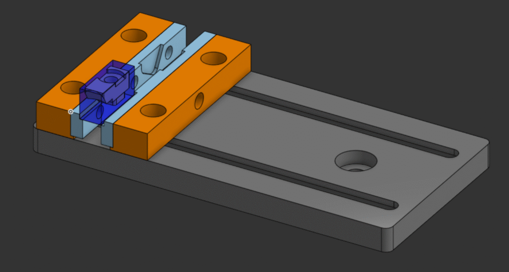
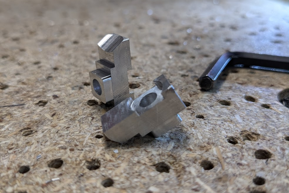
The first program I ran was to put a hole into a chunk of aluminum I cut on a bandsaw. I needed to use a smaller endmill to add it than I planned for cutting, so to reduce the number of tool changes and resulting z-zeroing issues I bored a hole into one piece of stock, switched it for the other, and bored that hole before I moved on to the cutting programs. For these, I put in a 1/4″ endmill that I’d use for all the rest of my toolpaths and cut out the top profile and features.
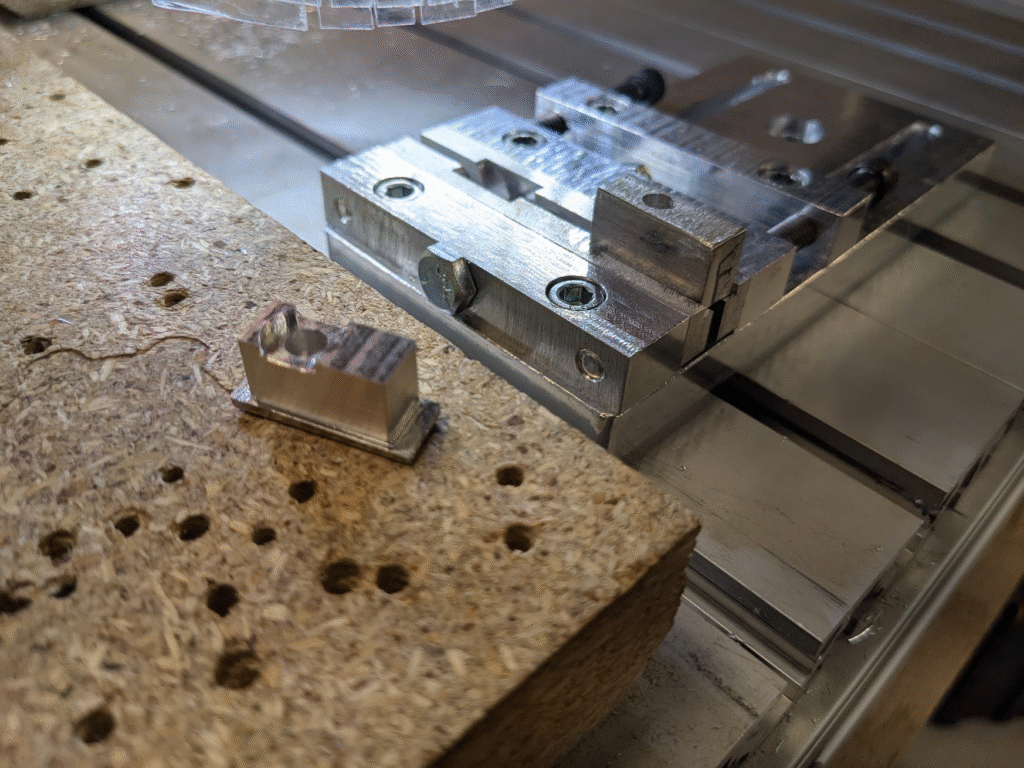
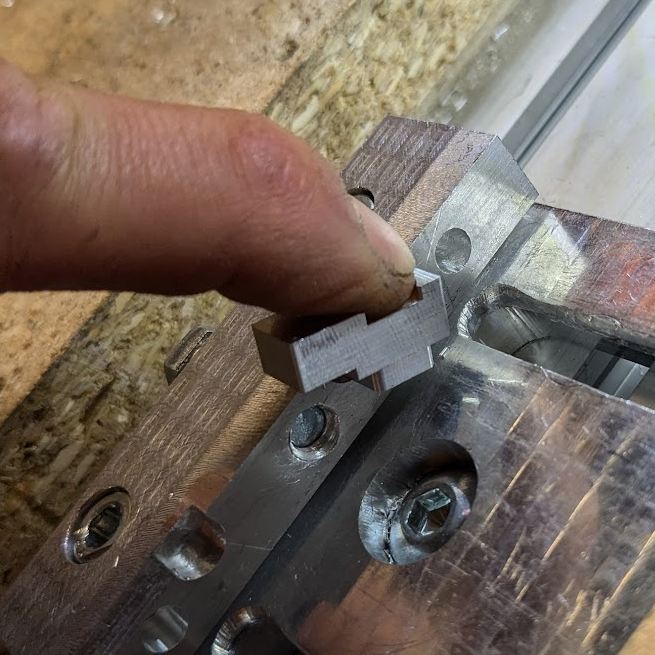
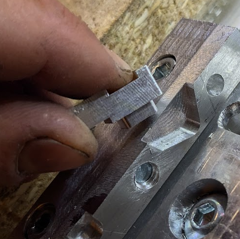
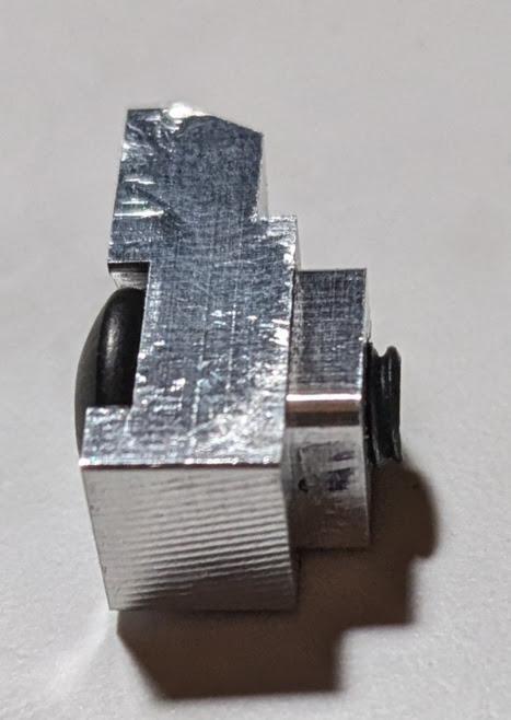
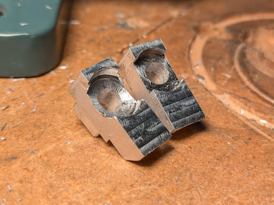
To machine the features on the bottom of the parts, I flipped them in my vise and secured one up against the hard-stop I used for the first operation. Almost immediately after I started cutting the first part, the tool yanked it out of my vise and slightly mangled it. What I’m pretty sure happened is that the back of the part was able to twist into a pocket in the jaw — there since a round cutting tool can’t directly machine right angles and I needed one — and come free since ti wasn’t resting on anything. To combat this, I went into my CAM software and reoriented the part so that the longer front was above that pocket instead and unable to go into it. I ran an updated program with the new orientation and no other changes and didn’t run into any other problems for both parts. Normally I’d have panicked and dialed down my programs, but I’ve had this happen enough times to know that I often overdo it. Also, I’d only put about 30 minutes into the parts so far and would have lost the one if I’d remembered to run my vacuum so I let my luck roll.
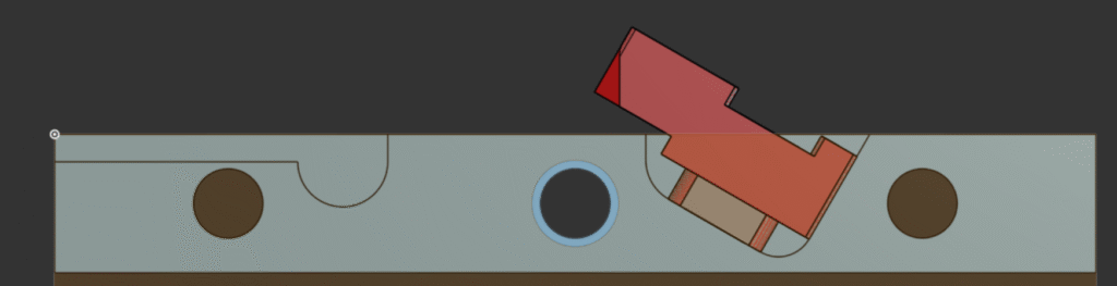
The last operation was the real reason I needed a custom fixture and was so excited to be able to run easily replaceable jaws, as I had to cut a 120 degree angle onto the front of the part. I used a pocket I put into my jaws to tilt the part upwards, which allowed the 3-axis machine to cut the profile. This is the first time I’ve done this on the CNC router, and it worked pretty damn well especially since I was dead-reckoning the location and orientation of the part as I kept the same zero for every operation.
Testing and Finalization
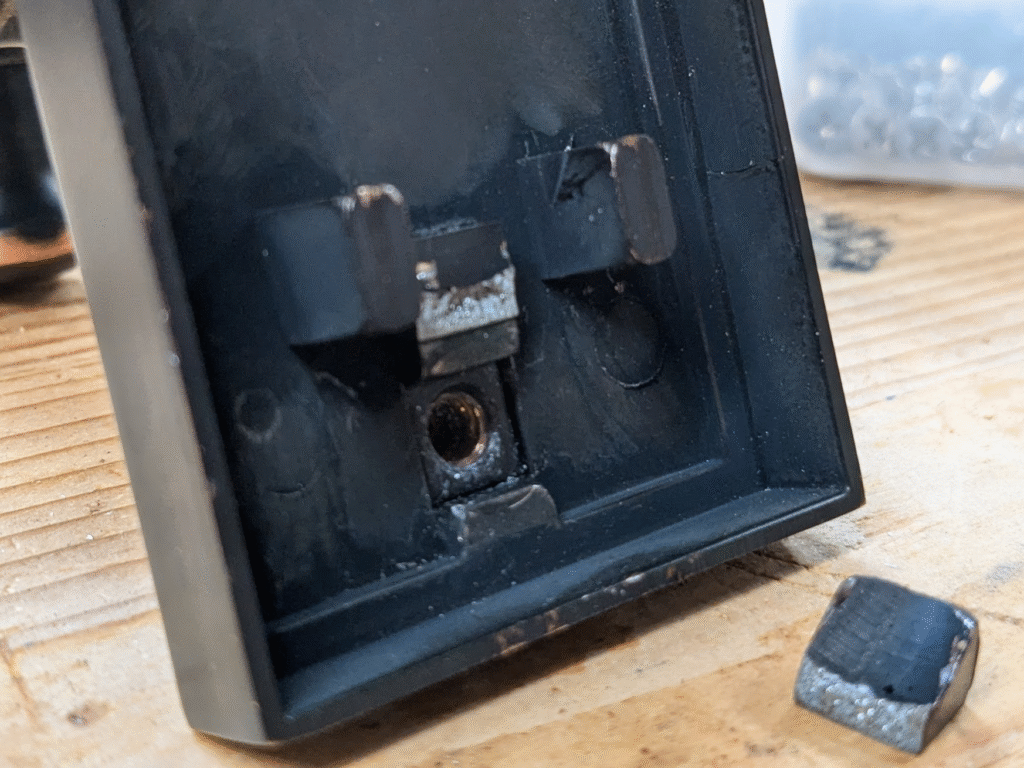
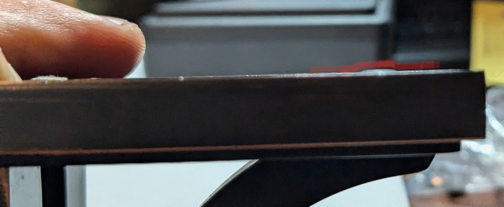
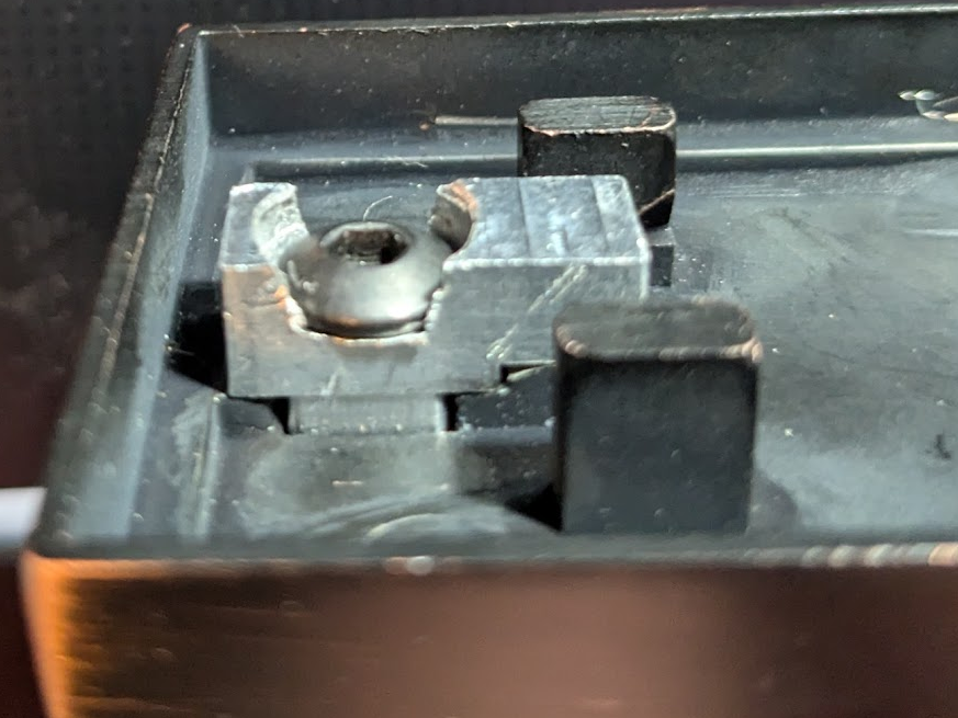
Attaching the freshly machined hooks onto the hanger, I saw a couple immediate issues. Newly acquired 1/2″ bolts that I designed around stuck up above the top of the base’s walls, which made the hanger unusable. When I put a shorter bolt on, it also stuck out and the threads didn’t reach far enough into the tapped hole to, well, thread. Using the same setup with a longer bolt as before for testing, the part worked fine so all I had to do to make it work was solve my new problems.
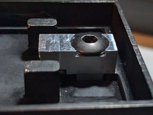
After some consideration, I figured the best way to make the bolts flush was to drop the bolthead pocket down more. The easy way, which I took, was to toss the part in a vise and use a flange-size drill bit — in a press for safety reasons — to cut it down. Alternatively, I could have machined new, modified parts but I was worried about having too little surface area for my second operation. Besides, manually drilling gave me direct control over the height without needing to re-prototype and I could stop and test as much as I needed. In the end, I drilled one of the sides deeper to account for some damaged threads in the base and, after testing, finalized the part.
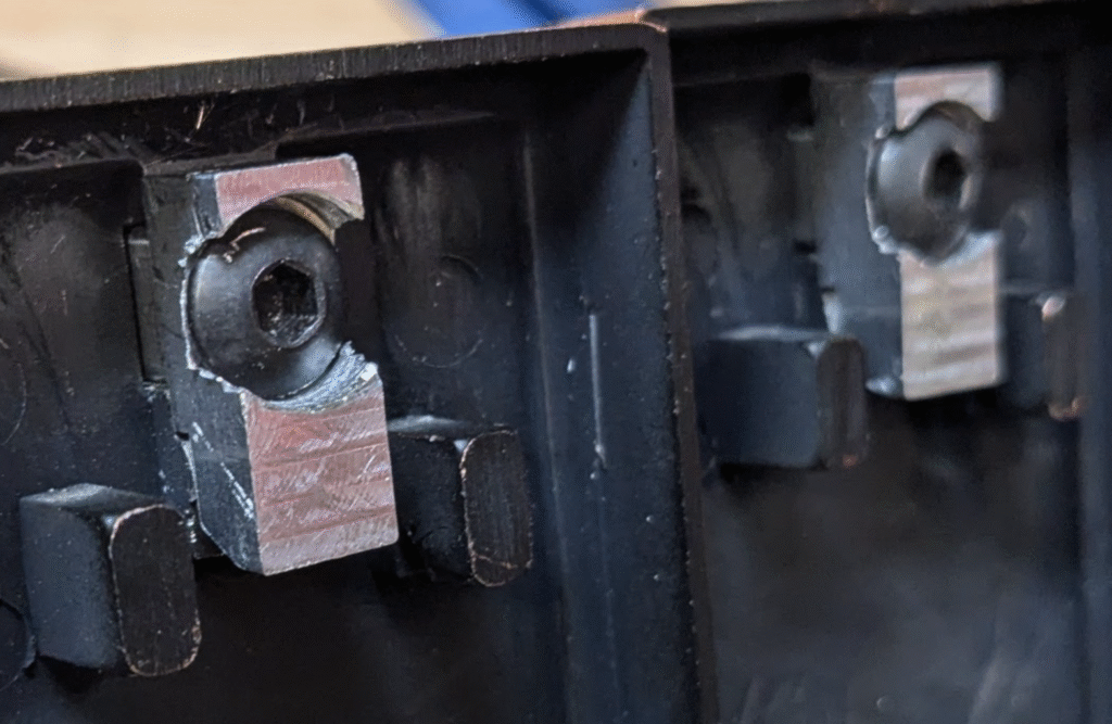
These replacement hooks should work just fine, and if anything breaks again I’d bet it’d be the threads on the hangers themselves — that’d be an interesting repair. This time around, I got to try out custom fixtures and removable jaws during machining, as well as practicing my more established skills like mechanical problem solving, rapid prototyping with 3D-printing, and intuiting how aggressive I can be with my milling programs. I also don’t often machine parts as small as these, which gave me a chance to do some higher-precision manufacturing.