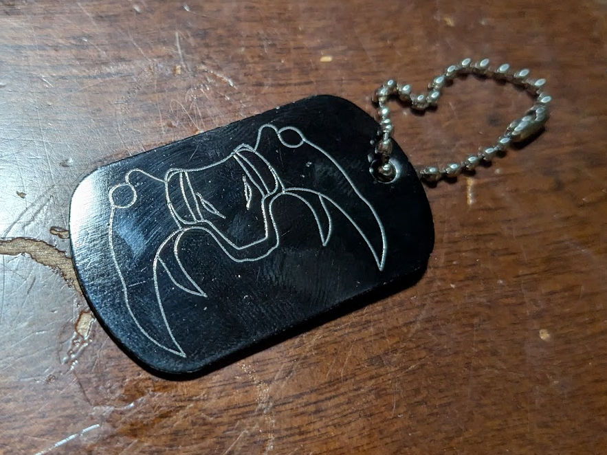
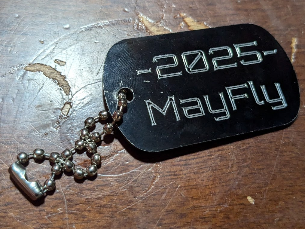
At my high school robotics competitions, teams often gave away little trinkets like buttons or keychains. During my last season I ran into a little box of 75 cent dogtag blanks at a local surplus store and figured it would be fun to engrave some to do the same thing.
This wasn’t a super intensive or impressive project, but in my opinion it’s cool enough and just technical enough to make a writeup about.
Method
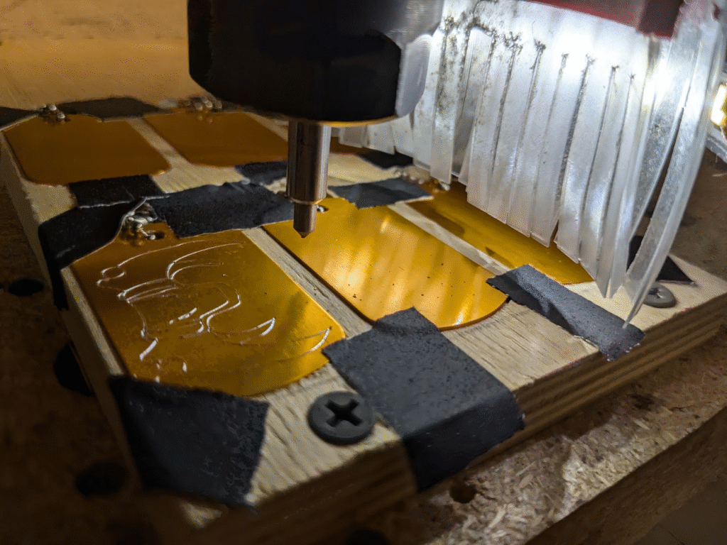
I could have engraved the tags by hand, but they wouldn’t have looked the greatest. My plan to get good results was to mount the tags to a CNC router, use an engraving bit to draw on one side, then flip it to do the other. This meant that I needed a digital model of the dogtag with some engraved features and a fixturing method that I could use repeatedly and reliably. The first fixture I wanted to try was using a 3D-printed block to elevate a tag and a vise to hold it.
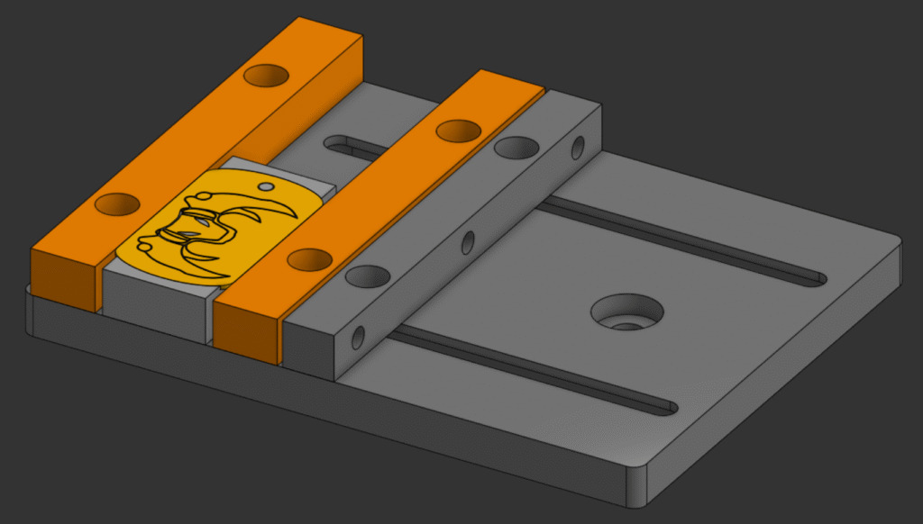
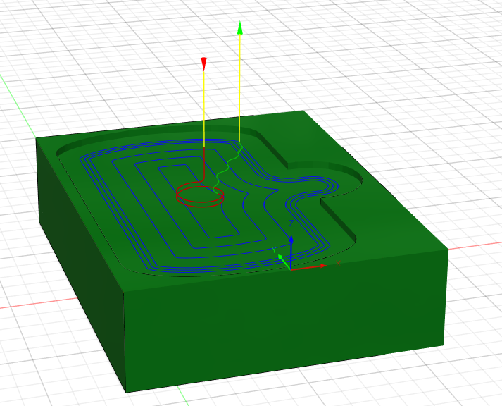
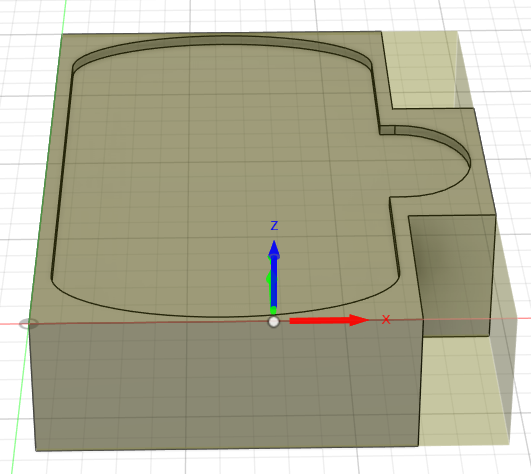
I wasn’t too satisfied with this setup, as it would be very difficult to keep the same zero position when repeatedly opening and closing the vise to swap dogtags. This also would require me to tighten and loosen 4 bolts for each side of each tag, which wouldn’t scale well. Some of my other go-to fixtures, like tape-and-glue or screws, wouldn’t work too well for the same problems of scale and complexity, but one that I’ve used occasionally seemed perfect: press-fitting into wood. I’ve explained this in other projects like my wrenches, but the gist of it is that I pocket a slightly smaller, negative profile of an existing part into scrap wood and slowly expand it closer to the part’s actual dimensions until it can be pressed in. For a proof-of-concept test, I bought a tag and modeled a pocket of it to machine, plus a slot to take it out. After a couple stepover passes to get the right press-fit tolerance, I tried engraving a tag and instantly ran into a problem.
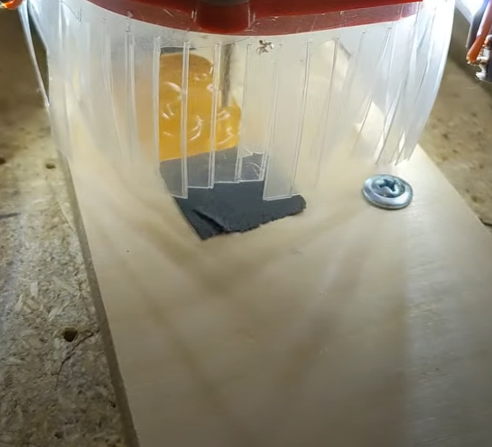
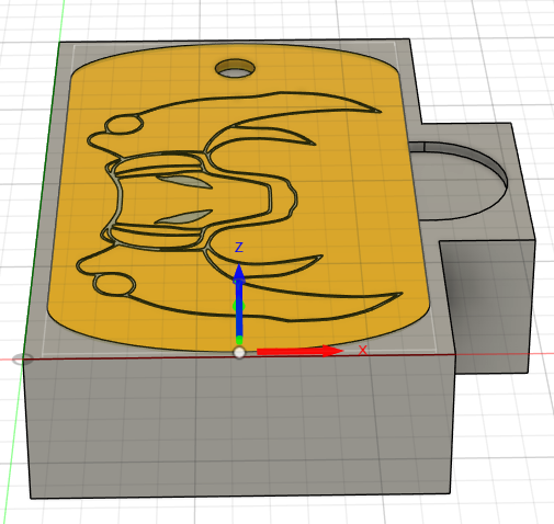
The way I organized my programs in Fusion, I had set the zero points of milling the pocket and engraving the tag to different positions. The whole reason I was press-fitting into wood was to keep the same zero for every operation so that I could flip the parts without changing it, but this accidental offset screwed up the top of the tag. Since I was running a test, I just brushed it off and worked out the zero issue in Fusion by playing around with what I included in the separate setups for the pocket and each tag side.
Scaling
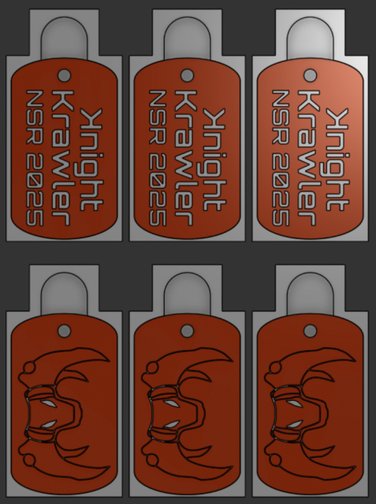
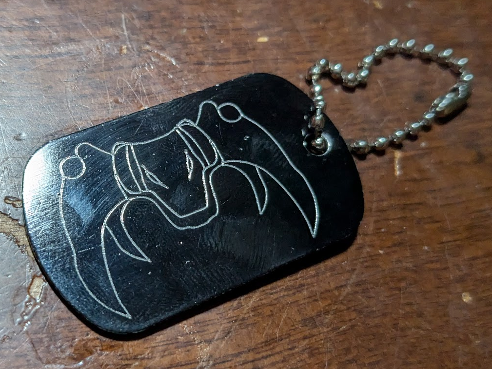
With a better understanding of how to go about engraving the tags, I returned to my CAD models and got ready to machine a larger run. I made a couple changes, like adding a deeper pocket to hold a string attached to each tag and arranging multiple pockets to do multiple tags at a time. To make sure that I didn’t wreck a bunch of tags, I ran another test to make sure that all the pockets press-fit correctly and that I had sorted out my zero-issue. After I was satisfied, I ran an engraving program that did the front of 3 tags and the back of 3 so that i could use the same program for all 12 tags.
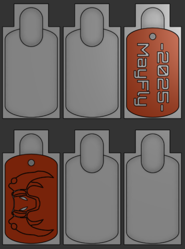
Across all of the tags in this run, I only had a couple issues. One was that some of the tags weren’t being engraved fully, which just needed a slightly lower Z height to fix. The other was that my XY zero got slightly off, but this time I set these zeroes to the bottom left corner of the wood I was using and could use it as a reference to get back on track.
Again, this wasn’t a very in depth project but it was a fun one. The people I gave the tags to thought they were cool and gladly took them, easily worth a small bit of cash and an hour or two of writing and running simple programs. This did give me a good chance to practice a technique I don’t often use, press-fitting, and has given me some thoughts on how to do better next time.