Seeing videos of professional machinists do full depth passes on thick pieces of metal, I’ve wanted to do the same thing on a router table. I can do full depth with thinner pieces I can screw down, or thicker pieces cautiously with tape and glue, but I can’t do both with either of those work-holding methods. With a vise however, I can mill thick stock with a bit less restraint.
Inspiration
My first thought on using a vise was to mount a small, standard shop vise. But, putting one on the CNC, it was clear that I needed a low-profile one. After doing some research, I found a vise on Amazon (pictured below) that looked like it could fill my needs and was relatively cheap, yet wouldn’t work too well for my application. Its jaws were really deep, which would mean I’d remove a quarter inch of material that was held in the jaws. Additionally, it was made of steel and any collisions would either damage the router’s gantry or break the tool. I did like the design of the vise, which seemed like something I could make to my own parameters, so I made my own.

Setting Parameters
Since I wanted to emulate the design of the vise above, I needed the jaws and base plate to be thick enough to hold a 1/4-20 bolt and a nut to fasten it. I had two pieces of nominally .5″ stock available, one about a hundredth over and one 5 thou below; I planned on shaving down the thicker piece close to .5″ and flat as I could, and then flipping it over and machining the base and jaws out of it. The overall size of the vise was determined by this piece, which could be milled down to an exact 3″x6″ base. With the width of the tensioner piece and jaws, which needed to each fit a 1/4-20 bolt to secure to the base, adding up to about 2″ I set the space available between the jaws at 4″ to give some tolerance on the ends and to become a nice even number.
CAD Modeling
I started modeling the vise with the jaws, setting their total travel based on the size of my stock as mentioned above. I made sure to include the tensioner piece in this sketch, along with where the bolt compressing the jaws would be located in the bottom left.

Extruding the jaws, I included pockets for 1/4-20 socket heads to rest in so that the top could be flat. I modeled a ledge for parts to rest on, although I planned to only cut it after the vise was installed to ensure that it was accurate relative to the machine’s Y axis. In addition to the ledge, I included the holes that the tensioning bolts would thread into despite planning to drill and tap those manually.
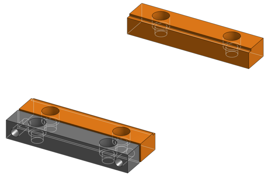
After finishing the jaws, I moved onto the base that would hold them. First, I made the silhouette based on the size of the stock and where the holes for the bolt would be located. Extruding this sketch, I’d have an envelope to work within and see its interface with the jaws. For the moving jaws, I made grooves that had tight tolerances to reduce play in the Y direction and make it easier for the bolts to clamp them down.


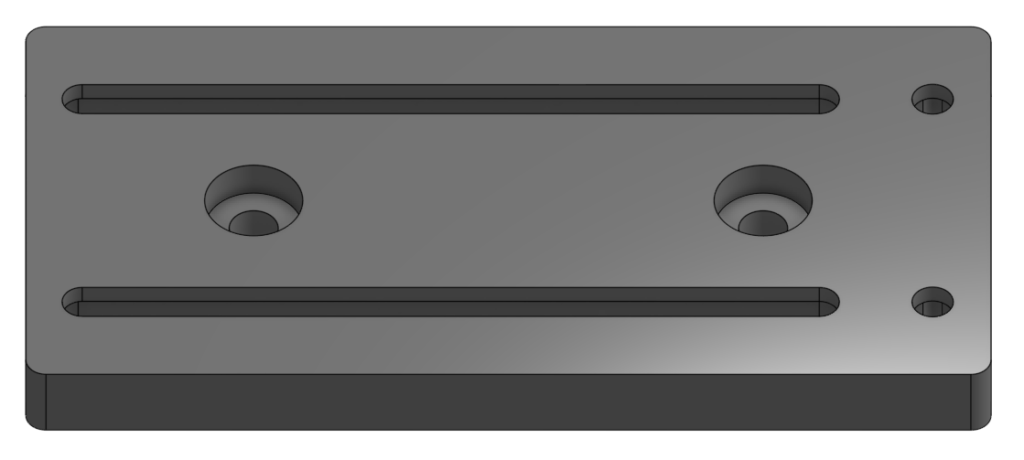
On the other side of the plate, the bottom that would face the CNC worktable, I added grooves and pockets for the nuts. I made sure the grooves were wide enough to allow nuts to slide easily, yet narrow enough that they wouldn’t rotate freely when I tried to tighten the jaws down. For the static jaw, I made a hex pocket with the same tolerance and made sure to add cutouts to the corners so that the 1/8″ endmill I would use to machine it would cut the whole pocket, rather than round corners it couldn’t reach.

Lastly, I added holes to mount the vise to the router table and a pocket so that the bolts wouldn’t imped the movement of the jaws. I positioned the holes to align with tracks in the CNC table, which I would slide T-nuts into for securing the vise.
CAM/Fabrication
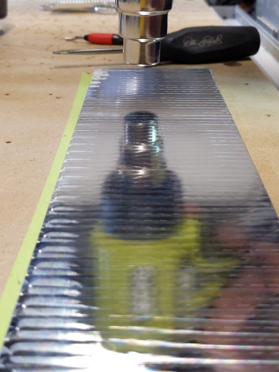
I started off the manufacturing process by taping and gluing down the thicker, >.5″ stock to flatten it, then flipping it to flatten the other side. The material needed to be as flat and dimensionally accurate as possible, since any tolerancing or unevenness in the vise itself will be transferred to parts made in it.
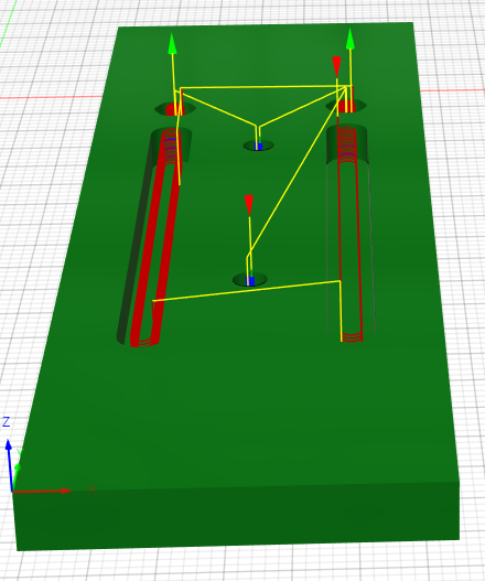
After both sides were faced, I left the material attached to the table and milled the bottom features. I used a 6mm endmill for all of these, since I designed every hole and pocket with the tool in mind so that I only had to change tooling for the last operation. Since I wanted this part to be as accurate as possible, I ran combinations of roughing and finishing passes on every feature to maintain a low tolerance. To finish off the pockets for the nuts, having used the 6mm to start them, I ran an 1/8″ endmill that could reach the corners of the pockets. As I switched tooling for these corners, somehow the machine’s work zero shifted slightly and the router cut about 1/2″ too far forward, which I had to correct for by changing my zero position on the router and in the program to a hole bored with the 6mm.

After manufacturing the plate of the vise, I secured the leftover stock from it to make the jaws. The size of the stock allowed me to make the moving jaw and the tensioner out of the same stock and operations, then the static jaw on its own. There were some non-flat areas, but I planned on running facing operations that would flatten them completely.
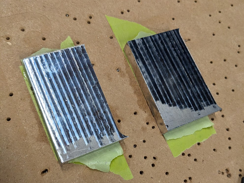
I started with milling the static jaw since I thought it would be simpler, however when I ran the cutting operation it generated too much heat and the tape let go. This not only scrapped the part, but it also snapped a perfectly good 6mm endmill that I couldn’t easily replace. For the other jaws, I learned my lesson and made a more conservative program making smaller passes with a better management of heat. Weary of breaking another good bit, I instead used a chipped 6mm that I was fine with breaking; unfortunately, this led to having a horrible finish on the jaws, but when in use that wouldn’t matter.


I made the static jaw out of another piece of stock and a better program, then I had some manual modifications to do on the parts. I tested the fit of 1/4-20 socket heads in their pockets, and had to expand the holes on a drill press. Additionally, I had to drill and tap holes for the bolts that would tension the moving jaw. When I had the jaws ready to be put onto the main vise plate, I realized I had put too little tolerance on the slots that bolts ride in; some time spent with a deburring tool cleared that up, and I was ready to test it.
Mounting/Testing
Initially to test the vise, I screwed a square to the wasteboard and secured it down with a couple screws; this wasn’t enough, and the vise was pulled off the table. A big part of the issue was the program, which I ran too aggressive, but holding it down with some screws definitely wasn’t enough. For further testing I’d have to mount it how I intended to later, on the tracks of the CNC table.
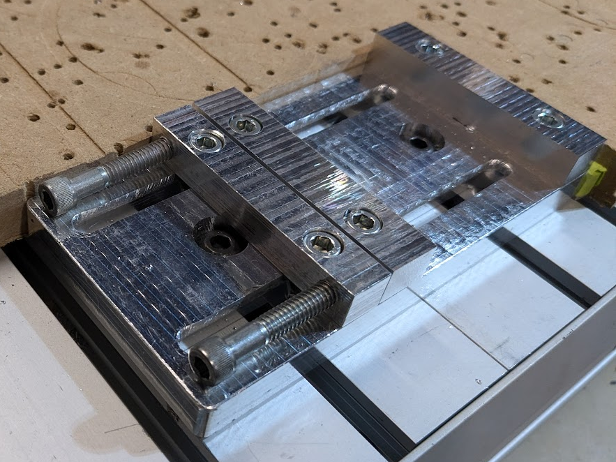
I setup a program to cut off a corner of the table to make room, then added pockets for boltheads on the main plate. These pockets couldn’t have been easily machined when I initially made the vise plate, being on the opposite side of the stock than all the other machined features. At the time, I didn’t have a good way to flip the material and keep it square, so I tried doing it manually using a large drill bit and drill press. The largest drill bit I had on hand was too small, so I tried another approach; using some T-nuts and bolts in the CNC bed tracks to hold the plate down, I zeroed on the individual pockets and ran a bore operation. This required setting zeroes very carefully, but it worked like a charm. With these pockets, I could now secure the vise to the table correctly, making sure to square it to be as accurate as possible and putting a wedge between the side of the vise and wasteboard to limit how much wiggle room I had. When it was attached, I closed the jaws and ran an endmill between them to create a flat indent for holding material parallel to the CNC’s Y axis.
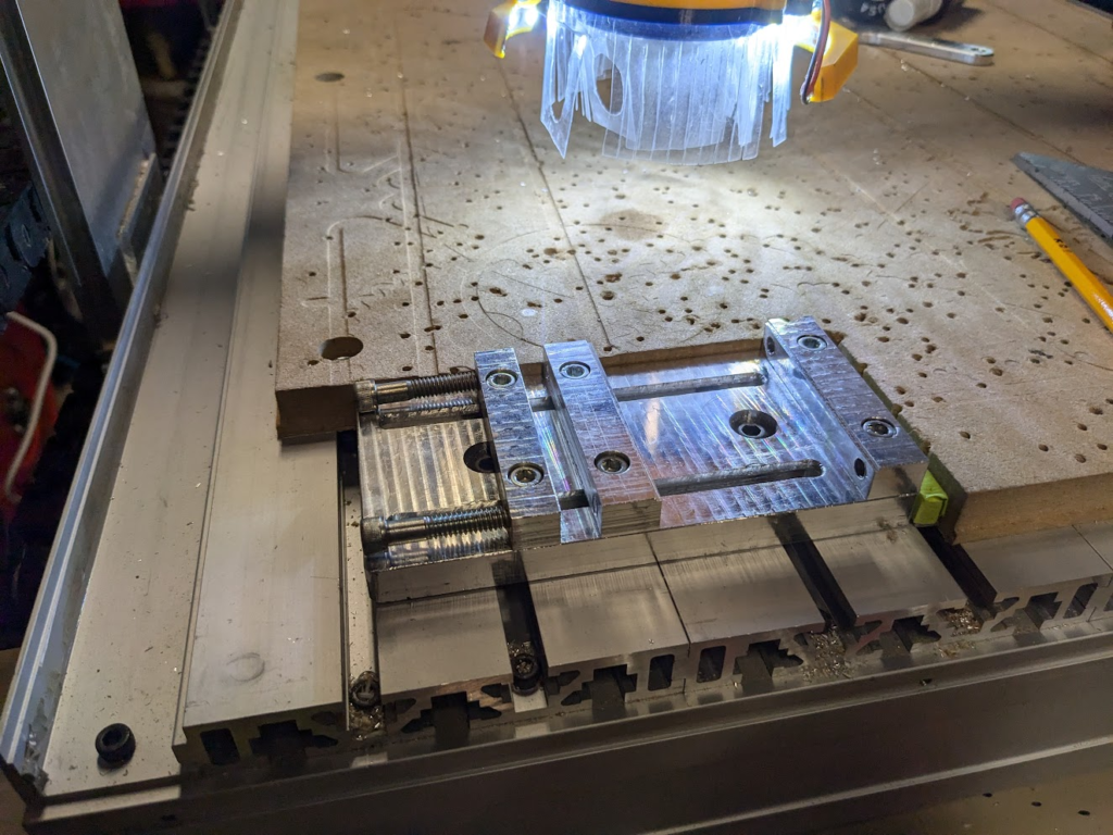
To test the vise, I figured the best and most beneficial way was to make more jaws, in case I needed to replace them. I found that I needed a pretty deep groove cut in the jaws to hold any material, so I ran an endmill down deeper and deeper into the jaw until I found a groove that worked. Once I got the groove worked out, I cut out one side of a jaw with some new endmills I was trying out. I left a ledge at the bottom so that I wouldn’t cut into the jaws, which I would run a facing operation on to remove. For some reason though, as I did the final operation before flipping the part I cut into the jaws. I thought it was an error in the program and it didn’t cut too far down, so I flipped the part, double checked the facing program, and ran it. Apparently what had been happening was that the endmill was slipping out of the collet, which meant as the operation ran it cut deeper and deeper into both the mounted jaws and the part.

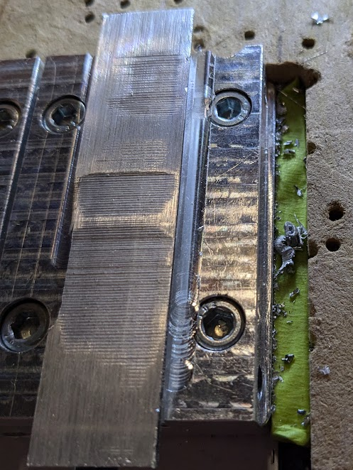
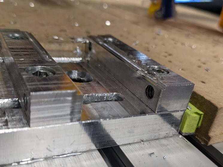
Despite mangling the jaws, the vise worked as it was supposed to so I considered that a successful test. I needed to make new jaws, though.
Milling New Jaws
There was a workholding strategy I wanted to try with these new jaws. To complement the tape and superglue strategy, I used the spindle to bore holes into the wasteboard that I could press metal pins into to align the stock. For the boring operation I made the edges of the hole tangent to my zeroes, so if I needed to flip the material or resecure it for some reason I could use the pins to continue machining the partially machined stock without even needing to re-zero.

Starting off, I ran a facing operation on one side then flipped the material to face the other side. Knowing I could easily recover a failed operation if the glue let go, which it did a couple times, I ran some aggressive operations to gauge how hard I could push the tape. When it let go, all I had to do was put the pins back in, re-tape-and-glue, and tone down the operation to keep going. After the final spring cut to ensure the jaws were accurately dimensioned and square, I put them back on and now had a working vise. Admittedly it isn’t the most secure nor reliable being made out of aluminum, but it’s been a fun project and can provide enough accuracy for my purposes. It ended up teaching me new workholding techniques and methods to achieve high accuracy, along with acquainting me with a tool used in industry.
Link to CAD Document – Vise