
The CNC router I’ve been using is water cooled, and its pretty obvious when its pump is running; it isn’t obvious, however, that there is flow to the spindle. I was tasked with making an indicator to show when coolant is flowing so that in the event of a jam it will be noticed and action can be taken.
I based the design of the indicator around purchased hardware, which consisted of two threaded hose adapters and a 1 and 7/8″ O-ring. The hose adapters had 3/8″ thread and I planned to have them on the side of the indicator, meaning that I would need to use thick stock to be able to fit the adapters. I acquired some 3/4″ stock, which gave 3/16″ of wiggle room for the placement of holes that would have to be drilled and threaded by hand: the router is 3 axis and doesn’t have a reliable way to reorient stock.
Initial Design
I started designing the indicator by defining variables and creating the basic shape of it, positioning the hose adapters to enter at the bottom of the pocket and have plenty of stock to thread into. I also determined the rough size of the part by adding stock on either side of the O-ring to act as walls.

I then extruded the walls and made a pocket for the O-ring, which I tolerance and made shallow enough for the top of the O-ring to be able to compress against the cover piece I would add later. I also included a post in the middle of the pocket, which would be cut out of the stock to serve as the axis of rotation of the spinning piece that the coolant would push. Normally, I would use a bolt going through the bottom rather than machine a post into the part, however this would hold liquid and needed to be sealed so a hole in the bottom would be inadvisable.

I used this initial model to position the holes to mount the cover and the whole assembly to the spindle. I initially planned to use four holes for both uses.


I then made a simple window that I would cut out of 1/8″ polycarbonate, and a simple spinner that had arms positioned to catch the coolant flowing from the inlet and outlet to show that there was flow.


I didn’t like this version very much; it was way too bulky, which was wasteful of both expensive stock and time.
First Redesign
To decrease the size of the part, I changed up the hole patterns. I kept the same initial sketches, however I used fewer spindle mounting holes and relocated the cover mounting holes. The lower holes decreased the wiggle room to mount the hose adapters, but still left a decent amount.

This allowed me to make the body more compactly, saving stock. I had to redesign the cover, which wasn’t too big of a deal. I didn’t change the spinner, and for fun I added a small engraved message for the CNC operator on this version.

I showed the design to the person who gave me the task, who unfortunately didn’t approve of my important message. They also thought that the bolts holding the cover on were spaced too far apart with too few bolts.
Final Redesign
For this redesign, I again kept the initial sketches and changed the layout of the holes. I added a two extra bolt holes to hold the cover, while moving the mounting holes to account for them.

After integrating the bolt holes, The shape was still pretty compact while also allowing enough stock around the holes to tap them.


For the window, I omitted the writing and made it hexagonal to utilize all the holes nicely. I also left indents to leave room for bolt heads in the mounting holes. Lastly, I rounded sharp edges to be more appealing. I showed it to the person again, and they approved.

Machining Process
I 3d-Printed the spinner on the inside, then started the aluminum part. I cut off a chunk of nominally 3/4″ aluminum from the stock I had acquired earlier, then used the glue and tape securing method I had just learnt to hold the work piece. Using glue and tape, while needing care to control heat generation, allowed me to not have to worry about using or colliding with hardware securing the work piece. A vice would’ve be more effective, however this CNC Router currently does not have one.

I started machining the piece using an 1/8″ endmill to get into the small holes and grooves of the part, which I figured out wasn’t long enough to go through the material as I intended. I had it go the deepest it could in the bolt holes, which was deep enough for tapping the cover holes and I would just drill through the mounting holes using what the CNC started.
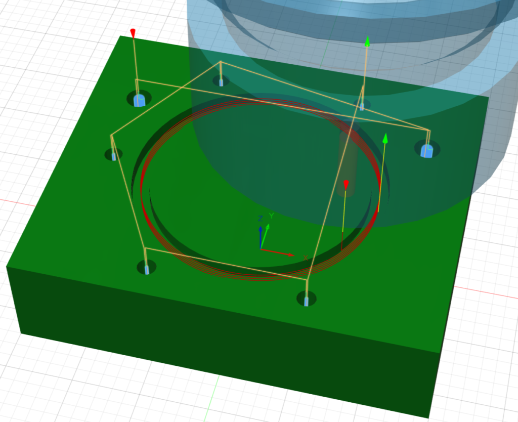
For the rest of the stock-removing operations I used a 1/4″ bi-flute endmill for its higher speed and resilience. I started with a facing operation to take the material from .767″ to an even .75″, then from there did a small pocket to lower the top of the peg in the middle to ensure it cleared the plastic cover piece.
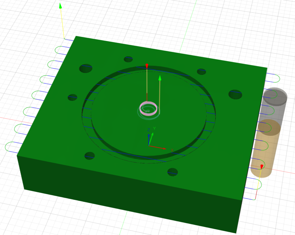
After the facing operations, I used a pocket on the interior with a small depth of cut to prevent heat generation. Fusion got confused with the peg in the middle and generated an overly complex toolpath, but it checked out and had no collisions so I ran it successfully.
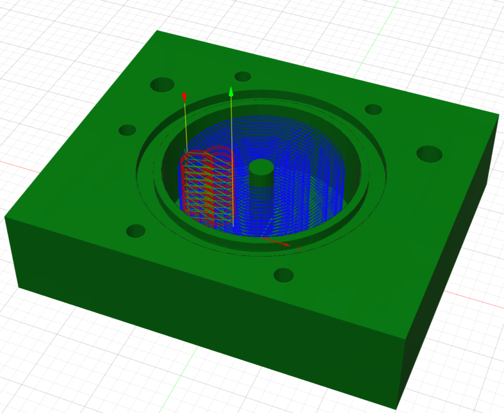
For machining the exterior of the housing, I used another pocket to remove excess stock and, despite plunging outside of the stock, only slightly deeper passes than previously to prevent excess friction and keep the tape from releasing.
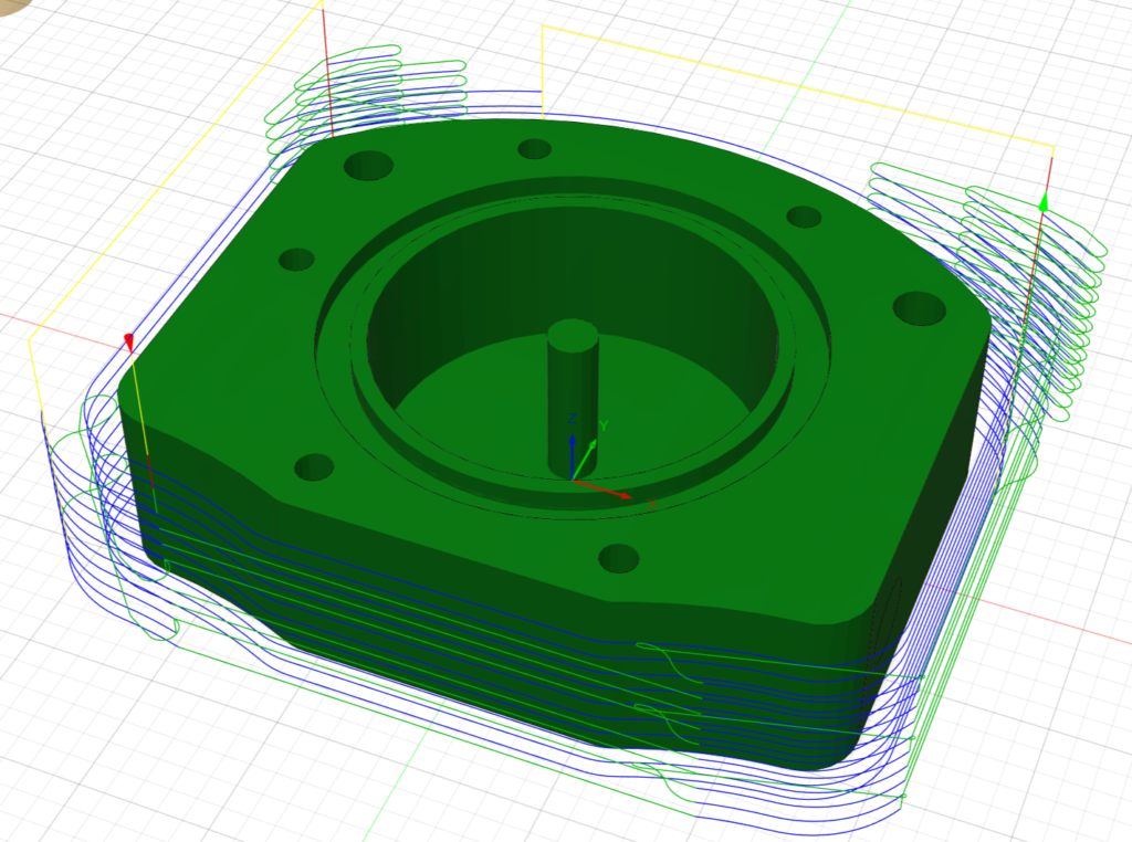
Lastly, I ran a quick chamfering operation to take off sharp edges and make it easier to install the O-ring. Somehow the zero point shifted, I suspect from the part shifting with some heat generation, and the chamfer cut unequally so I stopped it as soon as I noticed and re-zeroed based off of the center peg. I ran the chamfer again, and it completed successfully with only some hard to notice imperfections on the bolt holes.
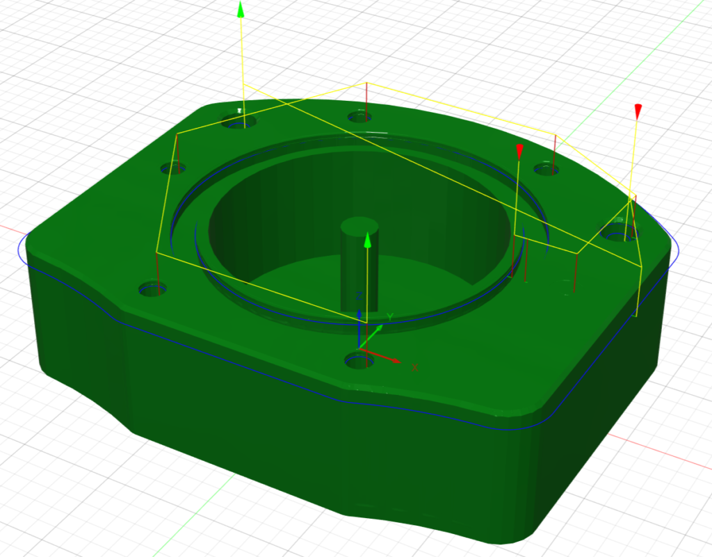

Machining the plastic cover was simple enough that I didn’t take any pictures, consisting of a bore operation for the holes and a couple ramping passes with tabs on sheet plastic.
Post-Machining
After machining, I took a drill to the mounting holes to finish the job the 1/8″ endmill couldn’t, then tapped the holes for the cover to the depth they were bored. I marked where the holes for the hose adapters needed to be drilled, then had them drilled and tapped.
I assembled and tested the assembly, then started designing the mount to attach it to the spindle.
Spindle Mount
I kept the mount simple, using the hole spacing on the machined aluminum part to make tappable holes on a 3D-print, then putting a ring with a slit on to attach to the spindle and compress to grip it. I printed it out of PetG since it needed to flex.


I bolted the assembly to the mount, slid it on the spindle, and zip-tied the mount to compress it and now it slowly spins when the pump is actively sending coolant through the spindle. It hasn’t leaked and is fun to look at, so I think this project is a success.

Link to CAD Document – CNC Flow Indicator