The CNC router I’ve been storing and improving for my robotics team has had a pair of wrenches for its spindle and collet since we got it, however they are made of ~.9″ thick stamped steel. I designed and milled two different sets out of 1/4″ aluminum cutoffs after having to straighten out a bend on one of the original wrenches that made it difficult to swap endmills.
Set One – Decorative, yet Usable

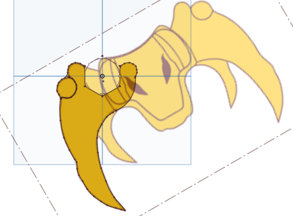
I started with these wrenches, which are decorative yet able to be used. I imported a PNG of our robotics team logo, then scaled and oriented it to align with a hexagon sized to a bit over 30mm to fit the collet on the spindle. I used the logo as a guide to trace out the shape of the wrench handle as a spline, making sure to separate the knob of the shoulder from the rest of the leg.

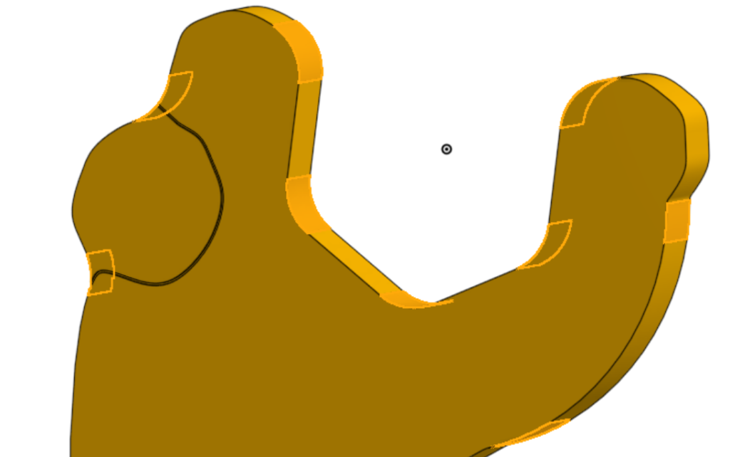
I made sure to round sharp, concave corners with a .24″ radius to make them simple to machine. It was (to me) important that it was painfully obvious that this was the leg of the logo, so I made a groove in both sides of the model to use to create a chamfer operation outlining the shoulder knob.


I scaled down the XY dimensions of the wrench by a factor of 21/30, which was a even .7 scale so that I could have a 21mm wrench to match the 30mm one; I kept the Z scale at 1 since I wanted to use the same stock for both wrenches. The rounded corners on the 21mm wrench had to be modified so that the same endmill could still round them, which took a simple “modify fillet” feature.

I machined the wrenches out of the 1/4″ stock cutouts from my swerve project, facing the cutouts to get a shiny, striped finish. I didn’t want to deal with using tabs or screws to hold the workpiece, so I used the superglue and tape method I recently learned to hold down the stock and cutout parts. To look nicer, and shiner, I ran a pocketing operation to surface this side of the wrenches and ended up with un-surfaced sections, which I left both to preserve the thickness of the stock and also since it was visually interesting. I wanted the dimensions of the wrenches to be accurate, so I took multiple large hogging passes at a slight offset to the part and did a final pass to remove the remaining material and leave a nice finish. I also made a spring cut after this final pass to ensure dimensional accuracy, then chamfered the perimeter and the engraved outline of the shoulder knob.
Since these wrenches are meant to be fun (ignoring the spike where you torque them), I wanted to try something fun with them as well; I designed a jig that allowed me to flip and press fit the wrenches into it, allowing me to secure them and chamfer both sides of the stock. In a separate tab I modeled a solid extrusion large enough to fit both wrenches, then brought the models of the wrenches into this tab and arranged them flipped over and protruding a set amount from the solid extrusion. I then subtracted the flipped models of the wrenches from the extrusion and expanded the pocket for the handles to allow an endmill to reach the tips.


I machined and used this jig with success, using an old plywood prototype from my first four bar project. The 30mm wrench could be pounded in and stay first try, while it took a few stepovers for the 21mm wrench to fit. The wrenches protruded about a third of the stock thickness, allowing me to chamfer the wrenches identically on both sides. I didn’t have to face this size, since they were already faced from my swerve project. The wrenches were removable by a flathead screwdriver, using the expanded pocket in the jig at the end of the handle. It took more work to machine both sides of the wrenches


Set Two – Pragmatic, yet Less Fun
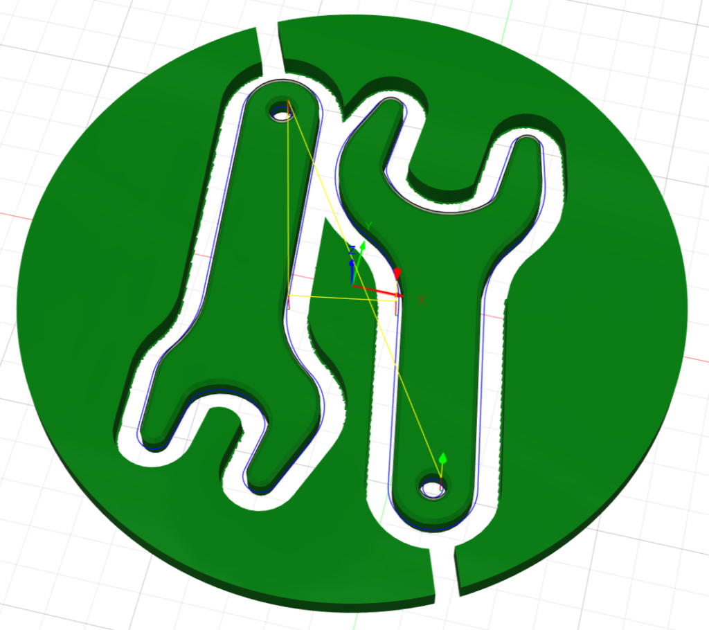
Starting these wrenches, I took a more conventional approach. The 30mm wrench got fully constrained and was dimensioned to have a good amount of material around the collet for strength and an angle on a good-length handle suited for making the wrench nice to hold. For the 21mm wrench I modeled it in the same way, not scaling it down as with the fun wrenches so that it wouldn’t be undersized. I also added a hole in a future operation, in case the wrenches ever needed to be hung on a peg.


Machining these wrenches, I used the same set of operations and work holding as before but omitted using the jig method. These wrenches didn’t need to look too fancy, so I just deburred the other side rather than chamfer them and wished that I had used my jig method as I got a couple new cuts on my hand.


After using both pairs of wrenches, the novelty of the decorative ones wore off and I’ve enjoyed using these pragmatic ones more. As a project, they were a good use of stock, a good chance to practice and improve less familiar techniques, and a good couple pair of wrenches.
Link to CAD Document – Collet Wrenches