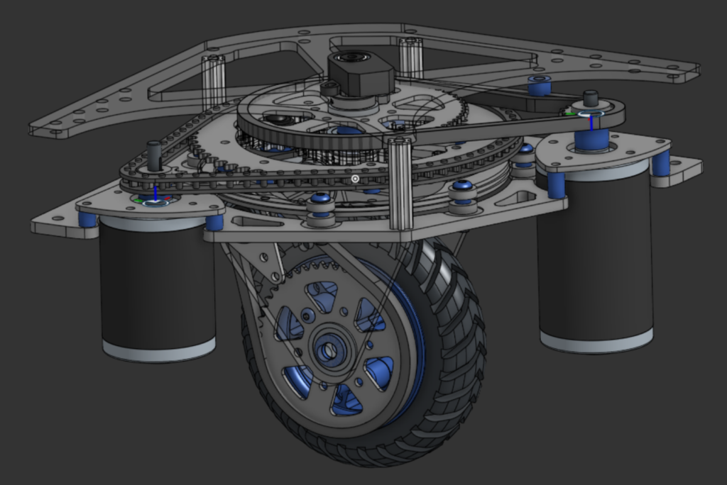
For years, I’ve been exposed to a type of robot drivetrain called “swerve,” where modules at the corners of the chassis possess independently rotated and driven wheels. This allows the chassis to strafe in any direction, turn in place, or even lock in position by turning the wheels. Most that I have worked with have 3 or 4 inch billet wheels, but none except for expensive industrial solutions are able to drive in rough terrain; to fulfill a dream I’ve had since seeing my first swerve module, I fully designed and fabricated my own oversized, rough terrain modules.
Constraints
Swerve modules go for about $300 to $400 apiece, which scales to between $1200 and $1600 for a square chassis. I had to pitch the idea to my robotics team to be able to use our existing hardware, sheet stock, and fasteners, so costs had to be minimal. This meant limiting the number of purchased parts and relying on parts I could machine or 3D-Print. I did initially start by designing around parts I could purchase, but I either modified or replaced all of these parts after calculating the cost off off-the-shelf parts I was planning around..
Initial Design
I started designing the module from the wheel, building upwards. I designed it to use a sprocket due to the scalability of chain, along with its slimmer profile and flexible mounting. To drive the sprocket I used an existing model of a pair of miter gears, initially intending to buy them since I lack the machining capability to make them myself. I also used an existing model of a small sprocket to connect the miter gears and wheel, which allowed me to calculate the initial length of chain needed and the placement of the sprocket

I used the location of the miter gears and wheel to create their mounting. They would attach to a side plate, which in turn would attach to a top plate via L extrusion. This top plate would hold gearing to drive the miter gears, so I made sure to include the location of key features to determine the needed gear sizes.


I then modeled the top plate and L extrusion, making sure to include a hex shaft hole for a shaft serving as the axis of rotation for the drive gearing as well as turn an encoder monitoring the direction of the wheel. After this I took an existing model of a #35 sprocket that I planned to turn the “turret” assembly and modified it to leave the middle open for gearing the turret. I also cut a little groove around the edge of the top plate for a bearing to ride in, which would be how the turret connected to the rest of the module.


With the plates for the turret made, I was almost ready to put it together. Before that, I assembled in CAD various shafts using existing part models. The motor that would drive the wheel would be situated away from the turret, so I attached a sprocket to the first stage of the gearing. For torque, I aimed to make the module as a whole to operate on an overall 1:8 drive reduction and a 1:6 turn reduction.


Below is the initial design for the turret, which was about 8.5 inches in diameter.

This design was too big, so I tweaked it to be taller and a lower profile. Additionally, I added a thin aluminum ring along the bottom to act as another surface for bearings to run along and hold the turret. I made the turn sprocket smaller and more open to allow more space for the gearing

With a turret to design around, I started modeling the housing. I started by figuring out the minimum dimensions of the module, leaving space for motors, and creating a sketch for each element of the housing to make it easy to modify. To figure out the motor locations, in one sketch I spaced the motors by determining what sprockets were available and calculating spacing based on teeth, while in another I placed the holes to mount the motors and yet another I drew a separate plate to hold them.


To attach the turret to the housing, I intended to use stacks of various sized bearings. I made a ring around where the turret would be of equally spaced bearing stacks, making the number of stacks variable driven so that I could easily change it if I needed more or less based on the weight the bearings could hold.


Using all the layers of sketches, I drew a profile of the housing to encapsulate all of the key elements and created the housing lower housing,

I had to create a separate plate to elevate the motors since their shafts weren’t long enough for their sprockets to be at the needed heights. These original motor assemblies consisted of small sprockets and spacers on adapters converting 8mm keyed shaft to hex shaft, all hex since I could get the models for hex-bore sprockets easier and use existing sprockets as starting points


After making the lower housing plate and motor assemblies, I made an upper housing plate. It only had to hold an absolute encoder in the middle of the housing, so I kept it simple to start off with.


The initial module, fully put together as shown below, served as a starting point. Since it had mainly purchased parts, I would have to replace almost all of the non-hardware components.

Iterating
One of the first changes I made was to redesign the motor mounting plates. I made them more compact and added extra holes for more mounting options. This version of them is pretty much final, although a change I would make it I were to redesign them would be to expand the hole for the shaft so that the sprockets could pass through it for easier motor swapping.

The next change was to change the gears and sprocket in the middle of the turret to be machined by myself. This would allow me to slowly make the sprocket larger and larger to increase the drive reduction along with making the module cheaper. I made the gears 10 DP so that I could fit an eighth inch bit into the roots of the teeth.


Final Sprocket
The sprockets I originally had on the motors were expensive for what they were, so I designed new sprockets I could cut myself and increase the drive reduction of the module. I made them out of scrap polycarbonate initially to test their dimensions, then out of aluminum for a more finalized prototype


I changed the shapes of the upper and lower housing plates, making them take less stock to machine and lighter. The lower plate also has channels cut out around where the bearings are mounted, which act to prevent the sides of the bearings rubbing on the aluminum part. I changed the bearing stacks themselves to use a different, cheaper bearing I had on hand; the original stacks had two large bearings and a smaller one sandwiched in between, however the new versions had a plastic spacer as the middle bearing was redundant. I later changed this to an aluminum spacer I cut, as the plastic spacer slowly compressed and caused friction related issues.


I wasn’t sure how many bearing stacks I would need, so I cut the new lower plate with a guess at the amount of bearings I needed and partially assembled (lower plate, turret top plate, bearing stacks) a module for a test. I put weights on top of the module, and found it could handle at least fifty pounds; I stopped there, since the max weight I expected to put on them was thrice that across four modules. This rig also let me test that the turret plate could rotate smoothly, which it could.
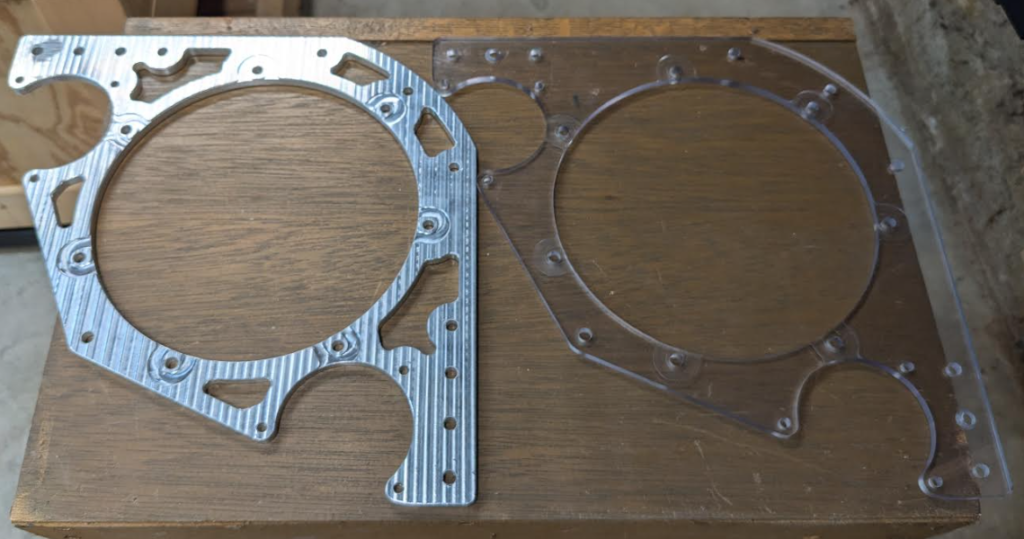
I made a physical prototype to test the fit and mechanical systems of the module, which I then kept rebuilding and replacing parts of until I was satisfied. The initial prototype used scrap polycarbonate for everything besides a few sprockets and small mounting plates. I 3D-printed Essential hardware and parts, like keyed shaft/hex adapters and the bevel gears, to test before having to purchase them. It was difficult to make this initial prototype since I had to set up toolpaths with an 1/8″ endmill to machine sprocket teeth, which I hadn’t needed to use on aluminum before; I made test-cuts of tiny sprockets to make sure that I could cut them with the correct tolerances and without snapping endmills. I also set up profiles for a 1/4″ chamfer bit to use on the aluminum sprockets to avoid having to debur the teeth.

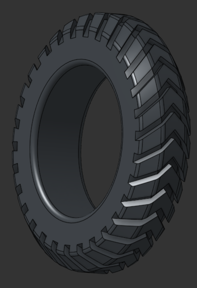
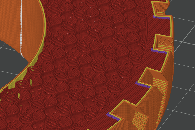
I didn’t have a wheel for the prototype, since I was expecting to have to purchase one. I modified the model I was using of that wheel to both integrate into the module better and to be able to be 3D-printed; this included 3D-Printing a tire out of TPU. I printed a low-infill smooth one to test before printing a finalized, stronger version that I added modifiers to in the slicer to make the tread of the wheel solid and usable up until it .75″ of wear.
Another improvement to the prototype was adding slots to align the sides of the turret to the top plate while still using L extrusion to connect them, however later I removed the extrusion and recut the plates to press-fit to the tabs. It’s more prone to failure than bolting on extrusion, however the press-fitted plates will constantly have over a hundred pounds pressing them into the slots so this is negated.

The main improvement to the prototype was, now that I knew that the main plate that connected the motors to the turret worked dimensionally, I could use limited 1/4″ aluminum stock to make a finalized version. The original polycarbonate version would bend when driving the motors, which made testing difficult; the aluminum, however, was more rigid and made the experience as a whole easier.
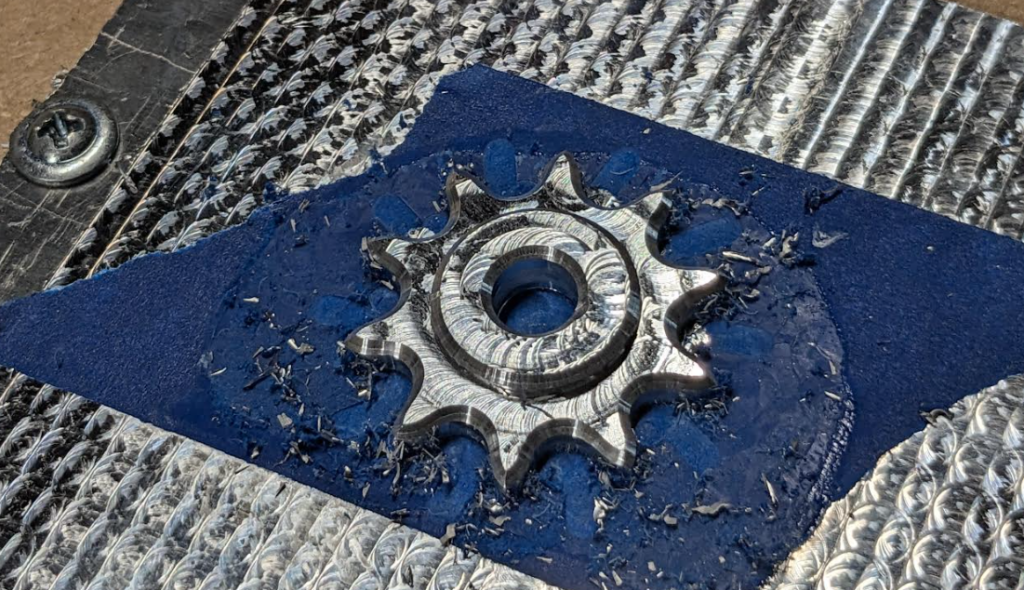
Yet another improvement to the prototype was using a scaled down motor to turn and changing the motor assemblies from using hex shaft adapters to machining the sprockets themselves to use keys. This decreased both cost and hardware usage, as well as eliminating a source of backlash in the drive and turn systems. This cause some issues in machining, however; I had been able to fit a couple screws into the hex shaft pocket to hold down the sprockets during operations, but I could only fit one in the 8mm hole. Additionally, the smallest endmill available to me was 3.175mm in diameter, while the keyways needed to be 2mm wide. I initially tried to solve the first issue by using tabs placed on the tips on the sprocket teeth, although these were difficult to remove and interfered with the chain. What ended up working was trying a method of work holding new to me, taping and supergluing. I took some scrap and flattened it for a nice surface to apply tape, taped the bottom of scrap stock I was using to machine individual sprockets, applied glue and accelerant between, and after tweaking programs (the stock kept getting flung away by the spindle) was able to fully machine a sprocket. The second issue, not being able to machine the keyway, was solved by the suggestion of my dad that I file a slot until it fits tightly. I had added the keyway to the model I machined, which with a chamfering operation left a groove to use as a guide. I filed 8 sprockets in total, which all now press fit onto the shaft with a key and stayed on with the help of a retaining ring.

Since I didn’t have the bevel gears I would be using on hand, and they were expensive, I doubled down on plastic versions and modified the models to work better. I made them both stronger and easier to print by widening the base, then individualized them; I lengthened the driven gear to eliminate a spacer and condense the shaft it rode on, while I added holes and screws on the driving one to allow it to lock onto it’s shaft to prevent it from sliding off. The plastic gears work in mechanical testing, however if they fail in actual driving testing I can either purchase the stock steel version, send the modified versions out to be machined, or change the filament used from PetG to Nylon, ABS, or even CF-Nylon based on future further testing. For now though, the PetG is final.

I reassembled the prototype with the new changes, and found an issue; the top drive chain was loose. I manually added a slot to put a bearing stack in, which I could adjust to add tension. I was ready to produce the rest of the modules, with a slight increase to the size of the drive sprocket. This took a rebuild of the prototype module, but I was satisfied to start gathering the needed stock and planning the machining.


Fabricating More Modules
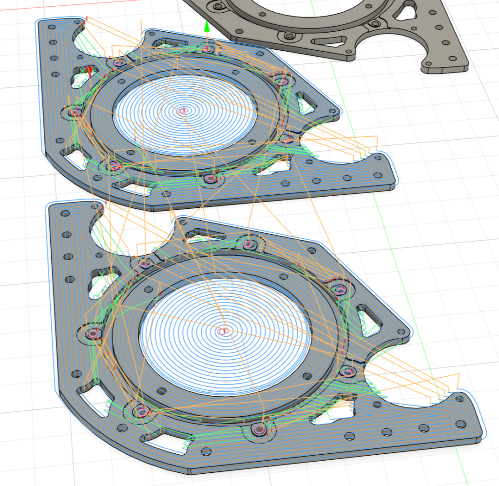
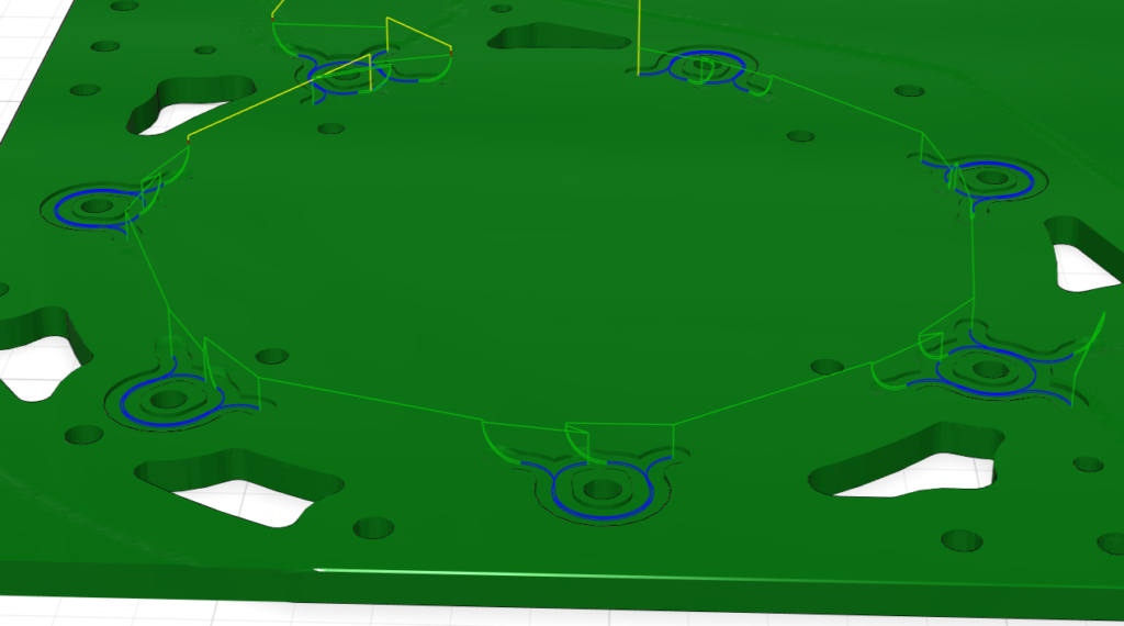
I started by 3D-printing the tires and the hubs they attach to, since those were the longest prints at 12 hours and 4 hours respectively. I had some issues with the TPU being too moist causing many failed prints, but with extensive drying the tires that made it through worked fine. Concurrently, I made manufacturing models of the parts I needed to machine in a separate document that reflected the size of the stock and had hold-down holes, then grouped parts together for export as a single file to allow me to prepare batches of parts in Fusion. I tried to reduce the amount of waste by saving the interior of large, open parts and using those cutouts as stock for smaller parts or usable scrap for later projects.
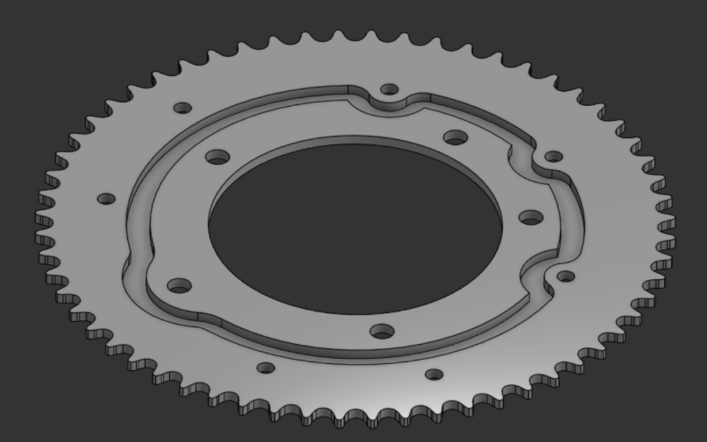


I didn’t have much experience with stock thicker than a quarter inch before this project, having cut only one part out of quarter inch aluminum. I tried quite a few new things on this thicker stock, like taking large hogging passes that entered from outside the stock or using more 3D aspects like inverse pockets on sprockets or grooves in the housing plates. I started using face operations or shallow pocketing operations to take an uneven surface and turn it into an in-tolerance, nicer to work with work piece. Starting to use facing operations really helped with machining the spur gears on the module, since I misremembered the size of the stock I had available as .375″ instead of nominally .5″ and had to plane down the stock an eight of an inch to be usable.
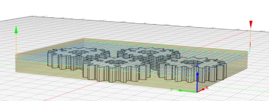
I finished printing and machining the custom parts, but had to wait a couple weeks for a robotics meeting I could attend to collect needed hardware and specialty items like shaft keys and retaining rings. In the meantime, I barely had what I needed to assemble a second module (the first being the prototype module retrofitted for the larger sprocket on the wheel); It took a day to make the second, after taking two months to make the first. When I finally got the rest of the parts, I took a day to make the remaining two and semi-finish the project. The modules just need encoders to be ready for use, which I am waiting on.
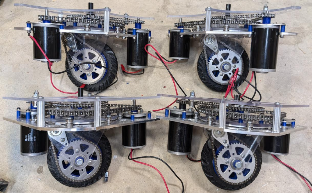
My exigence for making these modules was to have a rugged drive base to mount a T-shirt cannon to, which is currently being worked on by myself and other robotics teammates. Unlike the cannon, however, these modules are my own project and one I learned much from; I’ve used the techniques I tried on the thicker aluminum to machine .5″ and .75″ aluminum, held down by nothing but tape and superglue. I also now chamfer almost every part that I machine to limit the amount of post-machining deburring needed.
Link to CAD Document – 6″ Tire Swerve Drive