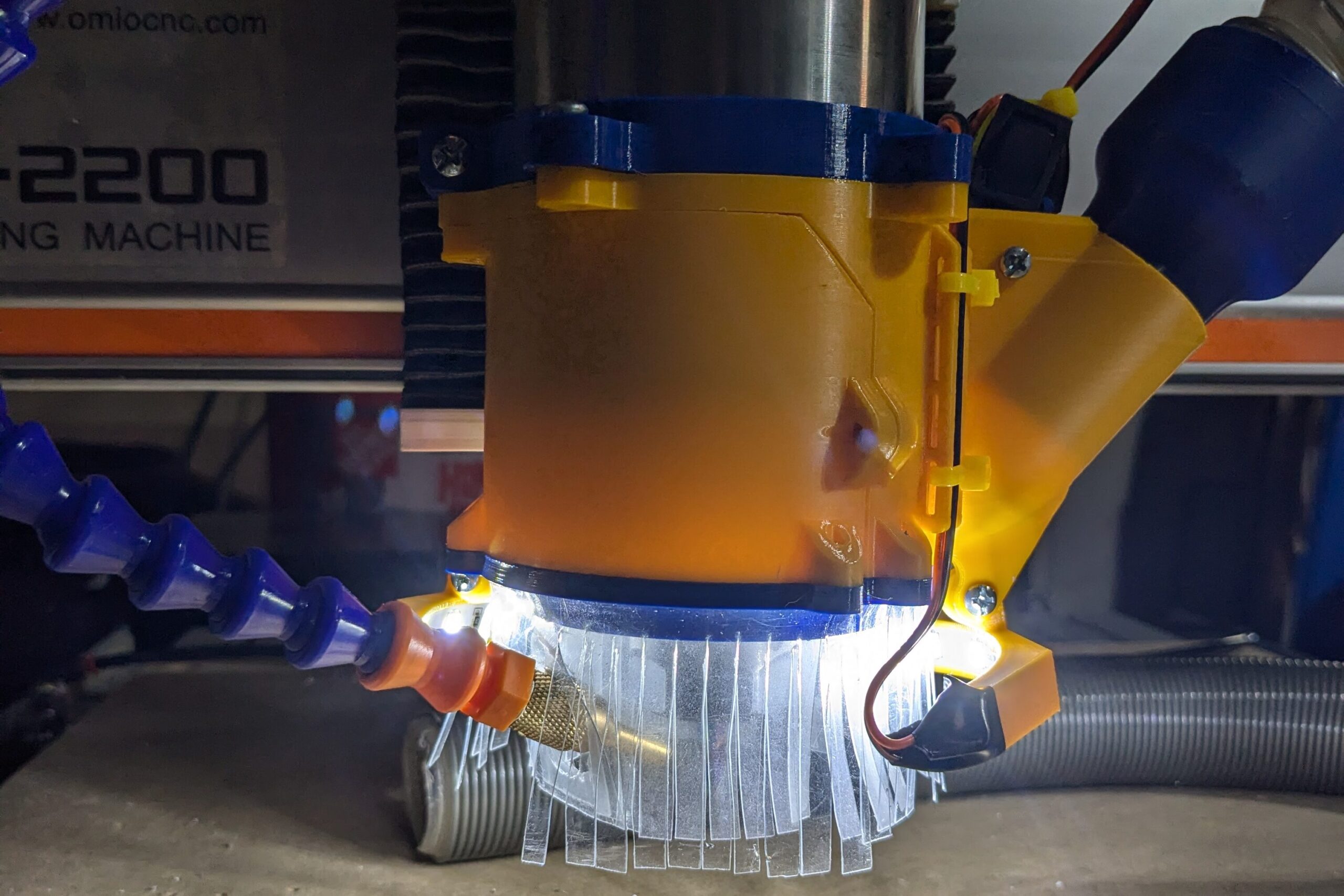
After a couple weeks of using R2DustShoe (the V5 Dust Shoe), I had some improvements I wanted to make on it. The newest version, V6.2 (aka See-3PO), was designed modularly without any dependencies to previous versions to make modifications as easy as possible
The main feature of this new iteration is the addition of spotlights, which are designed to be modular and fully removable. I wanted to see how much of a benefit lights would be prior to a redesign, so I added a mount onto the V5’s brush holder for LED strips. It was connected to a 9V battery through a simple switch, and I liked the concept despite its questionable look.
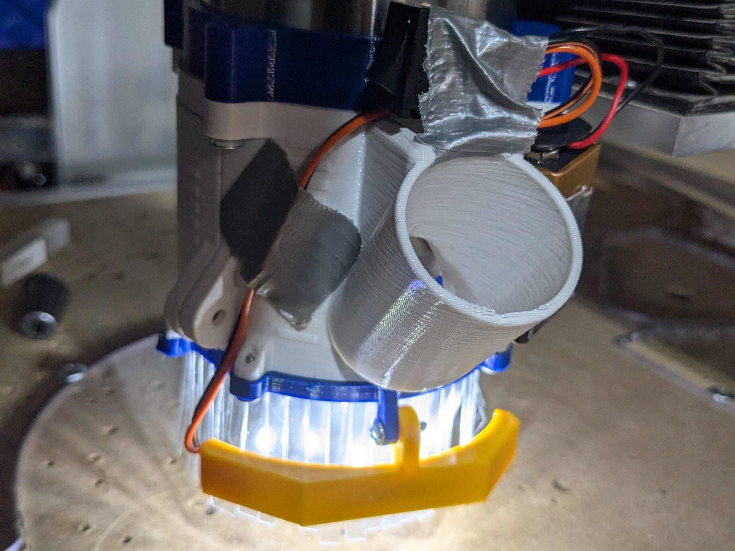
After testing with the V5 during cutting, I started modeling the V6. My goal for this version would be to have a properly cable managed, non-battery powered set of lights able to be removed or put back on easily. Instead of modeling it from the top down like the previous iterations, I modeled it in order of importance based off of a layout sketch determining key placements; brush mounting, spindle mounting, vacuum attachment, the body/cover, and a light switch mount. I also made the design as variable driven and modifiable as possible, as I had someone try to use my V5 design as a base for a dust shoe for a different CNC and run into errors with every change. I started with the brush and spindle mounting, as I see them as most important since their spacing and mounting locations determine the dimensions of the body/cover. A notable change to these parts from the previous iteration is that the holes for fasteners are countersunk to avoid the flathead screws that I use wedging into their hole and cracking the part, which made the brush mounts on the V5 need multiple replacements. This countersinking also lowers the length of the screws, making assembly quicker.
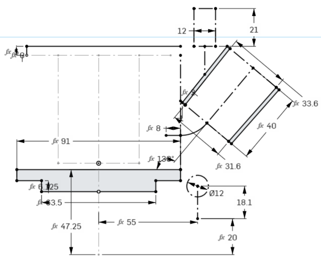
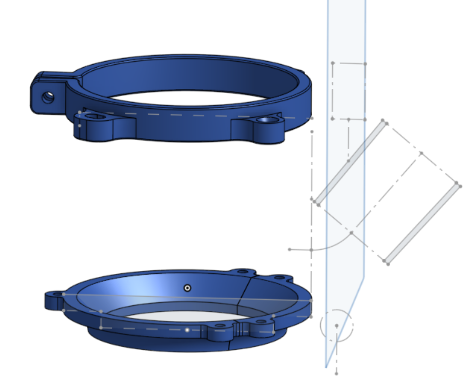
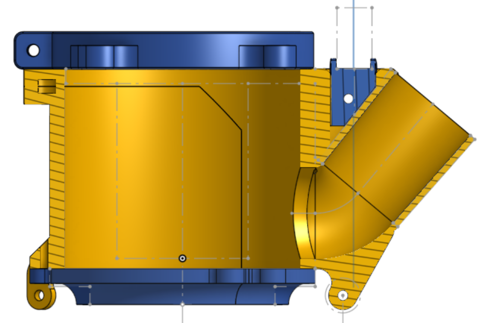
After modeling the mounts for the spindle and brush, the body could be made using their spacing and mounting as reference. I modeled the mounting for the vacuum first to make attaching it to the model easier, then modeled how the body would attach to the spindle mount. After that came the wall and various steps to make the vacuum attach correctly, and shortly after I could work on how the cover attaches.
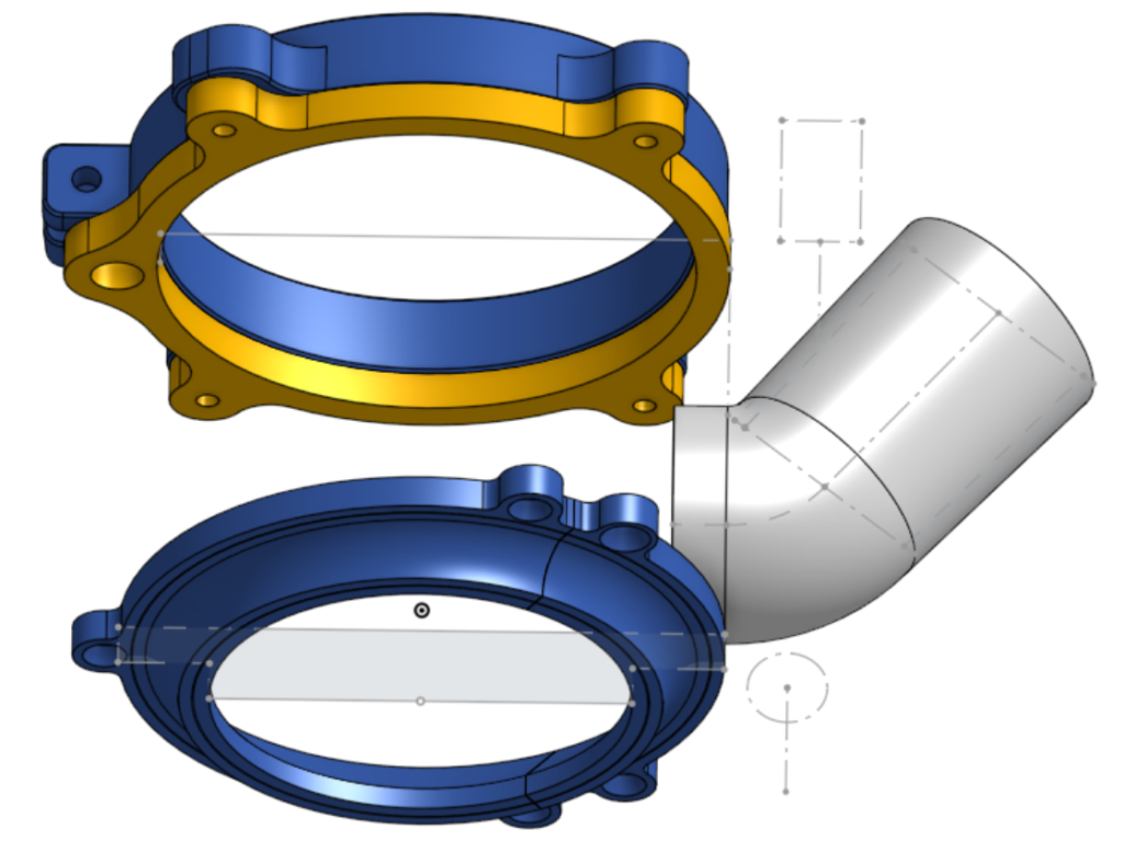
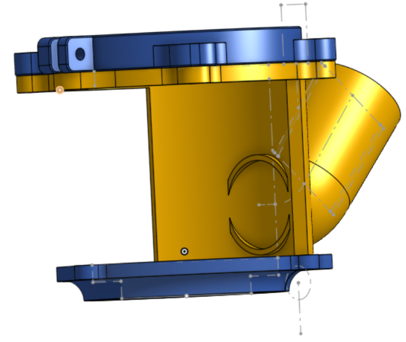
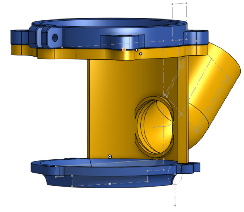
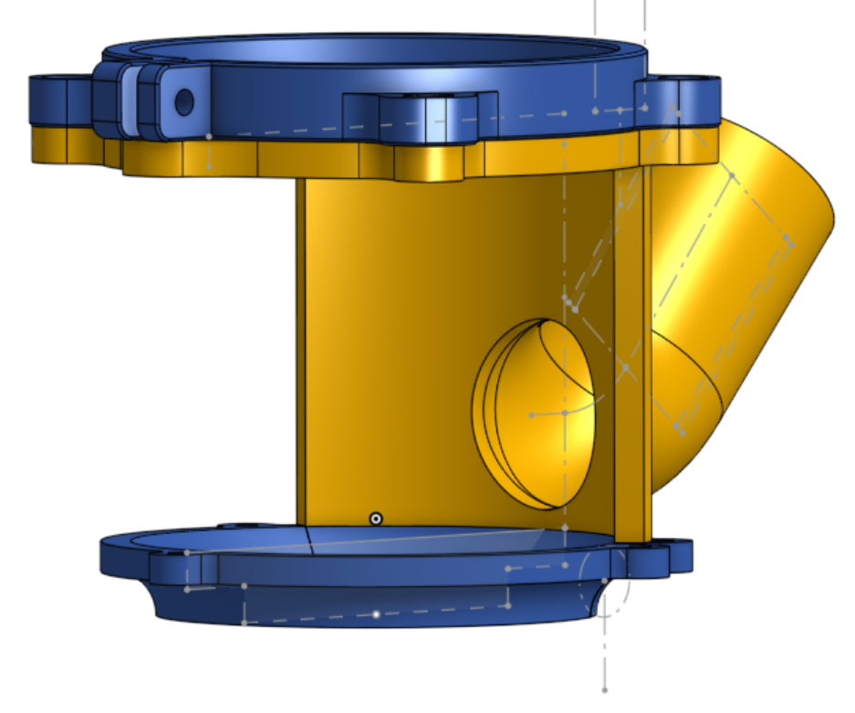
I made the cover attach the same way as previous versions, although I added a magnet in the back. The purpose of these back magnets – besides attaching the cover in a removable way – is to allow for current to be run between a set of wires while keeping the cover easily removable. Each wire goes into the hole in the magnet mount originally meant to help remove the magnet and is pressed against the magnet when it is installed, so that when the respective magnets touch they complete a circuit. By doing this I can have light from two different angles, convenient wire routing, and a removable cover simultaneously without needing a separate, battery power system for the cover.
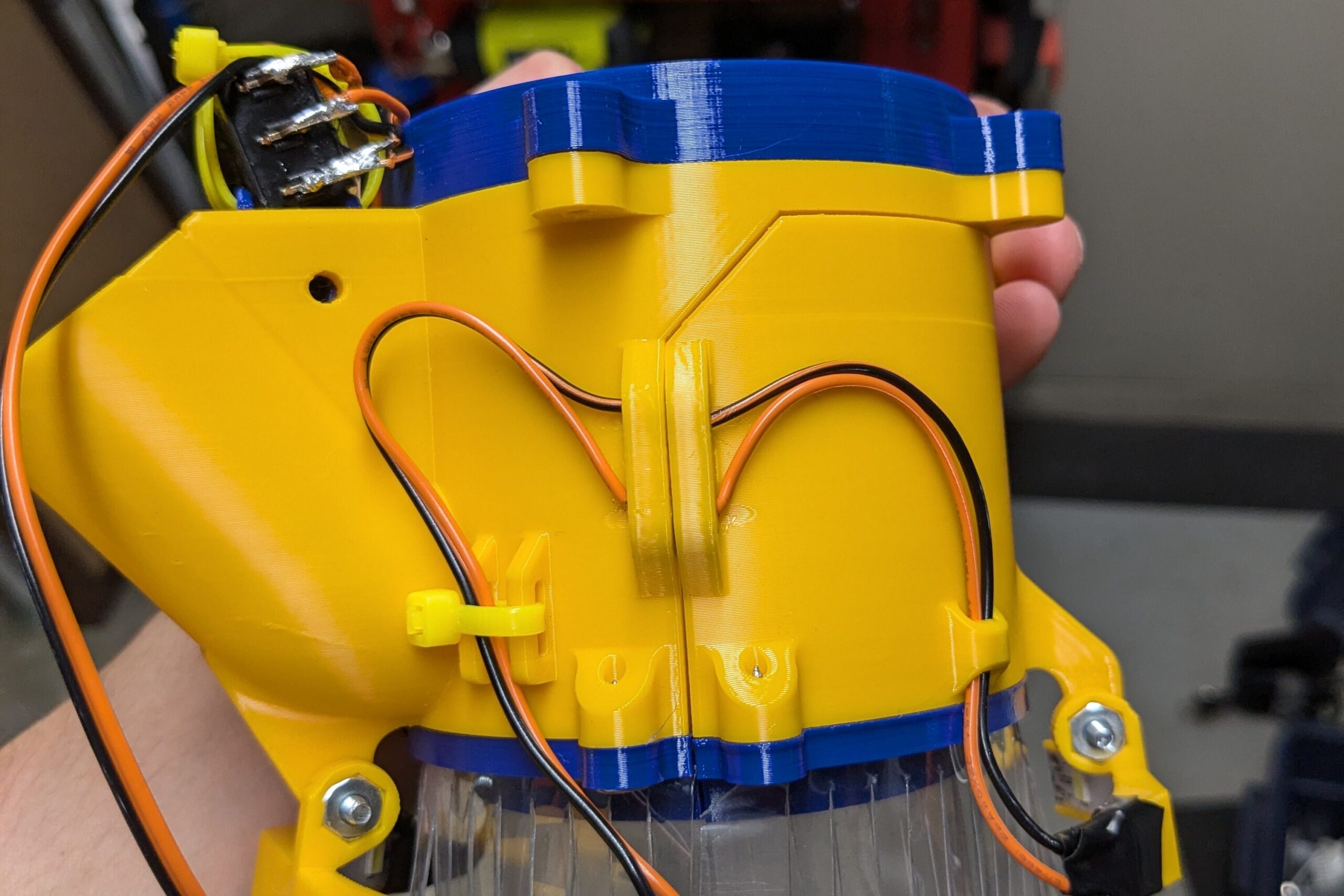
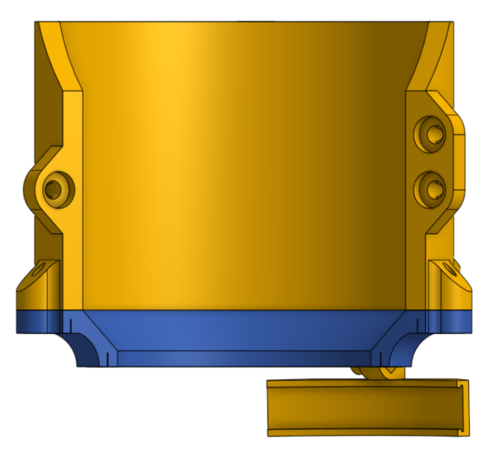
Modeling the rest of the design was very similar to the V5 (It was based off of it after all), although I made additions for wire management and mounting lights towards the end. The mounts are placed according to the layout sketch to keep the lights above the stock being cut, and if needed the lights can be taken off with some snips and a Phillips screwdriver. Along with the lights, I added rails on either side of the vacuum input for wires to be zip-tied and secured; similarly, I made a mount that slides and bolts into a slot in the supporting structure of the vacuum for securing the light switch onto the body.
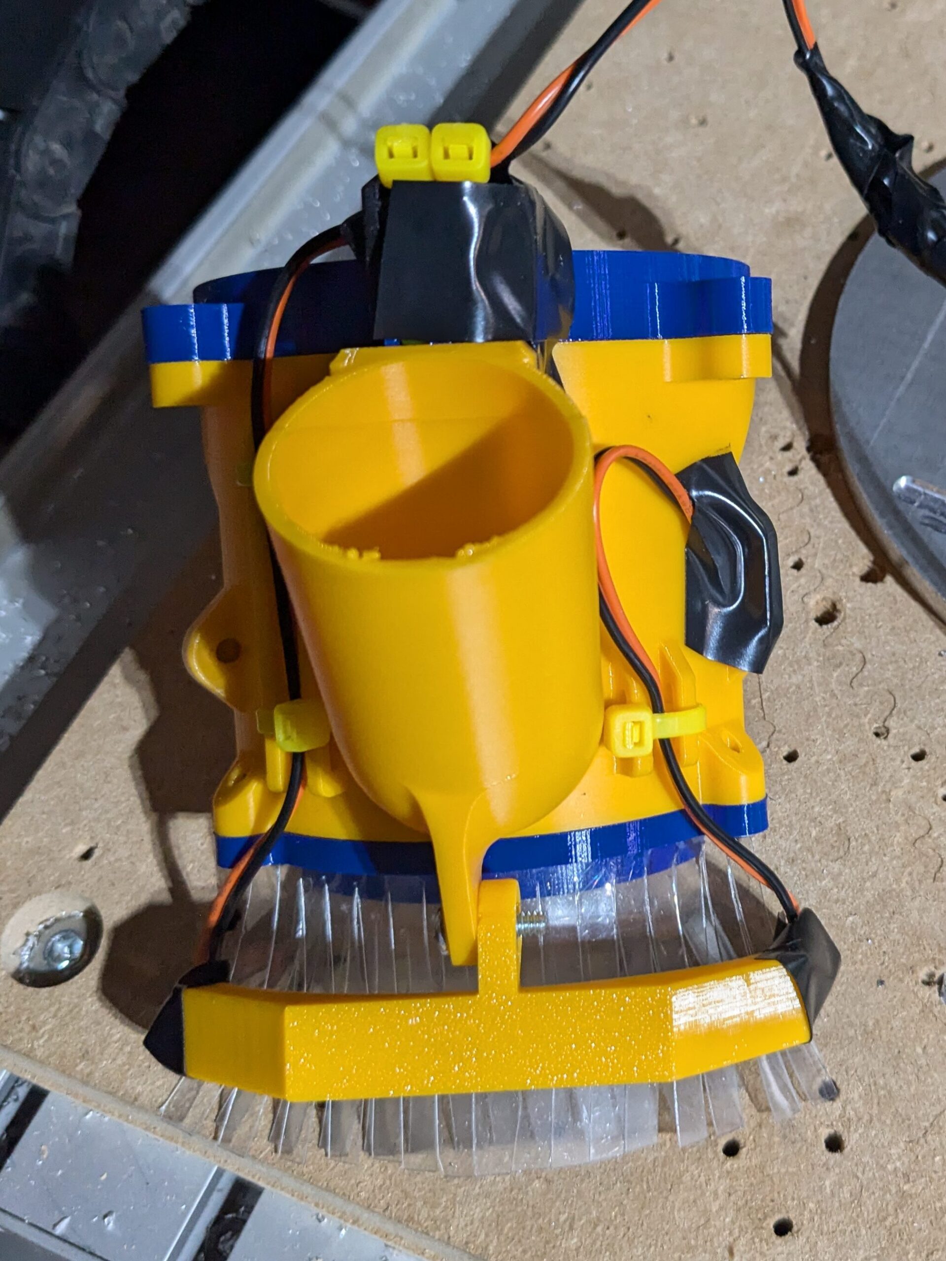
When initially testing this version, I had an issue with clearing the z-axis of the CNC. There’s about 1/2″ of clearance between the spindle and the z-axis, which I failed to account for with the V6. For the V6.1, I made sure everything had clearance. This version had some issues with print stability, which is why I had to make the V6.2.
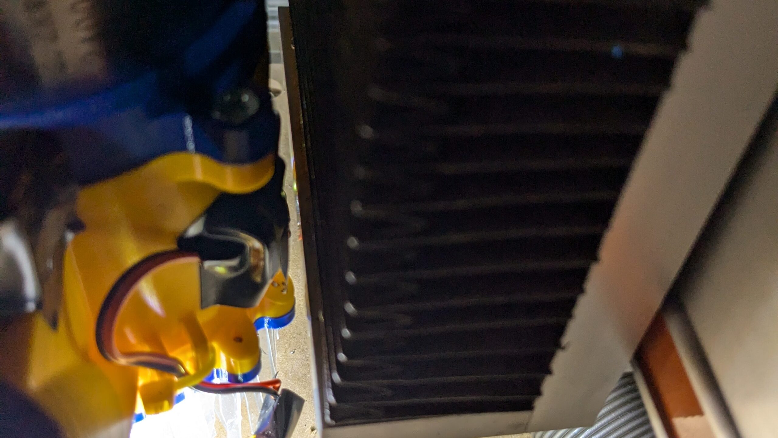
To power the V6.2, I opted not to use battery power. Not only does it add unnecessary cost and bulk, but it also means that the lights stay on when power to the CNC is cut. I used a power brick that takes 120V to 12V from the power strip supplying the CNC and coolant pump, then cut the end of a built in power plug so that I could splice a longer cable and an inline plug. It is then run through an existing cable chain (that controls the spindle and z-axis) to an inline plug interfacing with a matching plug on the dust shoe, allowing the dust shoe to be removed for replacement or maintenance. This was my first actual soldering project, so I learned a good amount about how to properly and easily splice wires and manage cables that I will certainly apply to later projects.
Link to Document – OMIO Dust Collection