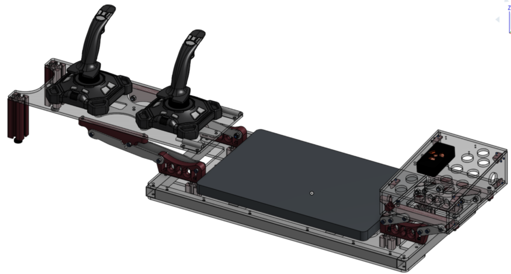
In the robotics program I was apart of, robots compete on a field during short matches. Before and after a match, their drive teams have a short amount of time to setup or pack up their equipment for driving the robot. As a result, it’s tradition and practically a requirement to have a drive station – housing for a laptop and driver controls – that can be quickly moved and easily transported. My team had an old driver station that was heavy, hard to carry, and couldn’t easily fit through doors, so I designed and built a more effective replacement for. Driver stations are seen by many people at events, so in addition to making an effective one I also focused on its looks, maintaining a color scheme and aesthetic.
Establishing Requirements
To be more functional than the previous station, this one had to fit four main parameters; being easy to carry, maintaining the height of the driver controls, maintaining the positions of the laptop and driver controls, and being able to fit through a 30″ door. Since the driver controls were originally spaced over 30″ apart, fulfilling these requirements would require moving parts; I got the idea of having a collapsing station by seeing another team’s station use a linear slide to become half the size and thought I could do something as cool.
Initial Design
My initial design was to attach 3D-Printed mounts for pairs of four-bar linkages to a single plate of 1/4″ polycarbonate . These linkages would attach to similar mounts on plates that would hold the driver controls, each arm having a hard stop against each other and the control plates. This would allow the station to be stored and moved in a convenient package while maintaining the old driver station’s positions of the controls (not modeled).
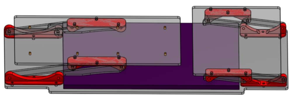

I started with modeling the extended locations of the controls and laptop, then the amount of space taken up by the controls when retracted. With these positions, I could then determine the locations and pivots of the linkage arms in both positions.
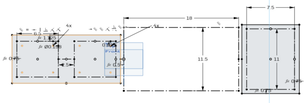


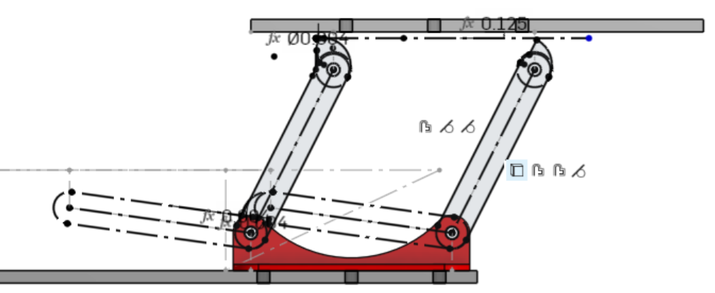
Having determined the placement of the arms, I modeled the arms for both control panels. I wanted them to have hard-stops at both required positions, so I modeled both sets of arms to collide when collapsed and have a strategically placed nub restricting movement. I started with drawing the left pair of arms twice, in their extended and retracted positions. I modeled the arms to press against each other when retracted, which would prevent them from moving farther down. They would be too far apart to limit their travel the same way when extended, so I used the geometry of the drawing when extended to design a nub, then modeled the same on the arm when retracted; pressing against the control plate, the nub prevents further travel. The final addition to this arm is a cutout on the lower one, since it would collide with the laptop mounted to the station with how low the pivots are. This severely weakened the arm, and made it less feasible to create.


I did pretty much the same thing on the right pair of arms, which were much simpler due to being shorter and having less travel. Both arms had nubs, although the right arm’s nub had to limit travel when retracted as the arms had too little contact.
The last component to this model was a pair of handles on either side, to address the issue of not having convenient spots to hold the station.
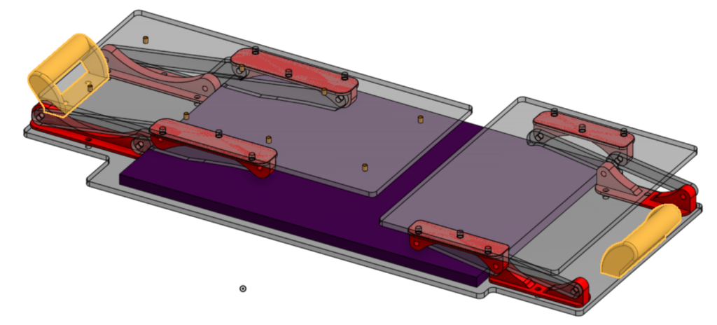
There were many problems with this design, including but not limited to this list-
- Very little material on its arms, limiting how strong/inflexible they can be
- Haphazard and likely ineffective ways of keeping position
- No structure on long plates to combat bending
- Very thin, small 3D-Printed mounting for pivots and handles
- Little accounting for what stresses the design might go through (force on top of plates, potential dropping of station, etc.)
- Little room for management of laptop cables and controller cables
Despite these issues, this design was useful. It served as a concept to demonstrate the ideas I had and get feedback from others, as well as showing me what I had to focus on for the next design.
Final/Manufactured Design
I had to start from scratch with the next iteration, although it would end up being very similar. It consists of two sheets of polycarbonate with an aluminum frame between acting as a base, connected to the control plates by pairs of four bar linkages. Some improvements include greater rigidity, very stable controls, and built-in handles and storage space. The color of objects is accurate to the manufactured version, with red/maroon as 3D-Printed PetG/CF-PetG respectively, opaque gray as aluminum, and translucent gray as plastic (acrylic for base, polycarbonate for all else.)
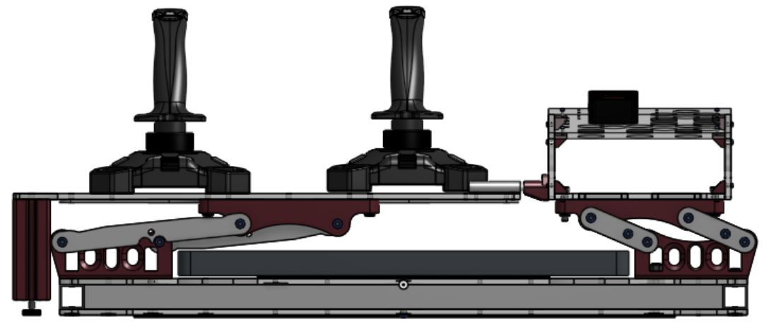

I started, like the original design, by modeling the open and closed positions of the station. I did both as construction sketches on the XZ plane to provide a front view of the collapsed and open positions, making it easier to model due to being able to use the open position to constrain and visualize the closed position. It isn’t modeled in the sketch – but probably should be – that there would be supports for the joysticks hanging off the side; I did account for these with the length of the bottom section. It should also be noted that I used the size of the plates in these sketches later on as a guide to the maximum size they could be, so they aren’t accurate dimension-wise but are accurate position-wise.


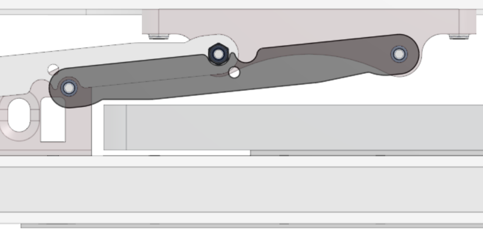
After modeling the two positions, I modeled the travel of the first pair of arms. Unlike the previous design, where the arms were on the same side of the pivot mount, I didn’t worry about the arms colliding with each other. I opted to design the arms to be on opposite sides of their mount, allowing for a farther collapse and thicker, stronger bars. This would mean that I would need to create some form of catch for them, which ended up as a notch resting on the bolt head/nut of the bolt that served as the other bar’s rotation axis. Another thing I did different to the previous design was raise the height of the pivots, which gave more clearance for the laptop when collapsed and in turn allowed for the arms to be wider. I did need to create a slight cutout in the arm when collapsed to protect the laptop, but it was less extreme than needed before. The last major change in this pair of arms would be the decision to have both the open and closed positions be at the same height, which allowed for various benefits. While making the collapsed state taller and correspondingly slightly less compact, it allowed for the use of the station even when collapsed by keeping the controls at the same height, the same design of physical stop for limiting the travel of the arms, and a more secure extended state that requires the linkage to be intentionally moved to collapse.

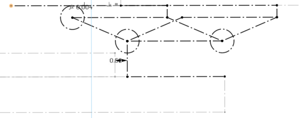
Modeling the travel of the second pair of arms, I made the same improvements as I did with the first pair. Since they are shorter and the travel less extreme, they don’t have to be on opposite sides; they just don’t ever hit each other. This means they need some form of catch to limit their travel, like the first pair, which I would later model in as a bolt that hits their pivot mount. To prevent cantilevering and damage to the arms, I modeled an arm on both sides of the mount for the bolt to span between.
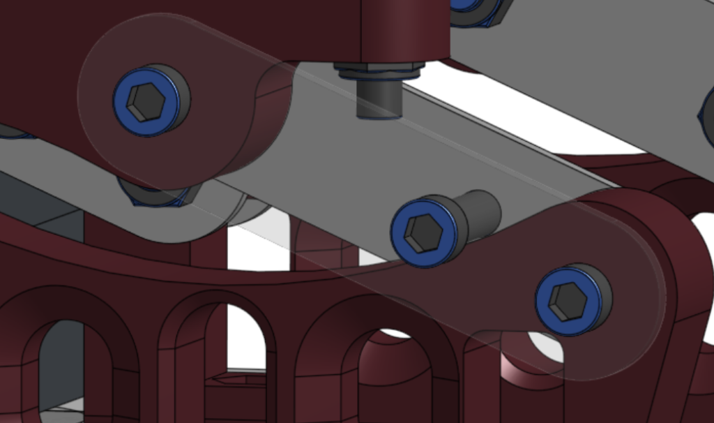
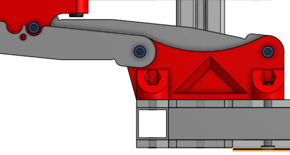
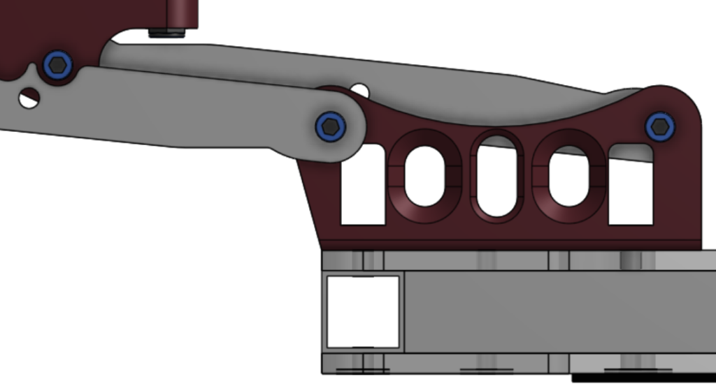
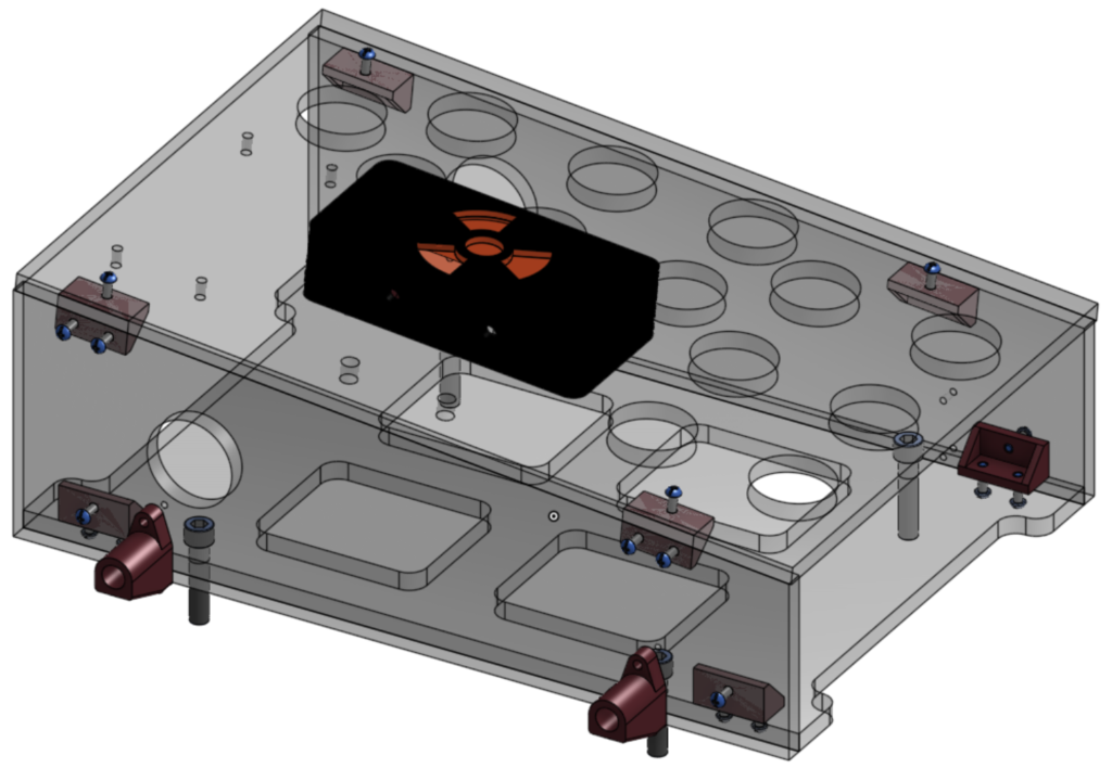
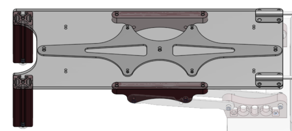
With the position of the plates and the pivot points of the arms, I could create the mounts connecting them. I started by creating the 2D shape of the mounts, then put holes to put bolts through the upper mounts to attach them to their respective control plate. I also added hexagonal cavities for putting press-fit nuts. After this, I designed the lower plate that the mounts and laptop would attach to to determine where to place mounting holes for the lower mounts. I used this first to create the initial mounting for the left lower mounts, which made the part a 3D object. I would remove this mount later and slightly tweak its corresponding 4-bar to use the right side mount as a result of some complications of its shape; it needed to be 3D printed upright, which made it a slow and weak print since the layer lines were aligned in a way where they were perpendicular to the direction force was applied, undermining the strength of the part. Despite that issue, the wide base of this part was useful in testing; I built a linkage and added a thick dowel rod to the upper mount to test how firm the linkage with a supporting structure would be, with good results.

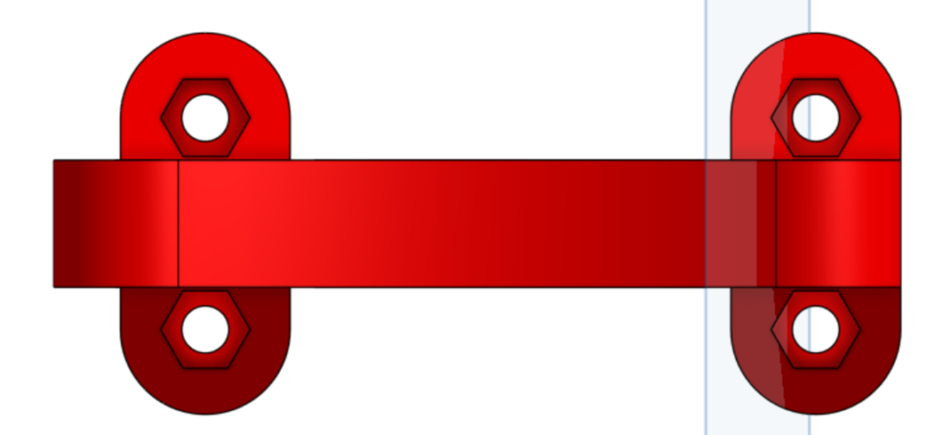
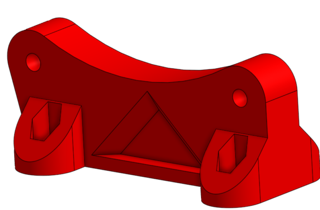
For the lower right side mount, which eventually would be just the lower mount, I also used the lower plate to determine the placement of the holes of the mount. The mounting space available was low due to the location of inbuilt handles in the plate, so I decided to put the mounting in the middle of the part rather than creating offshoots to mount to. This meant that I needed to create a slot to be able to get a fastener into the mount, which I designed to accommodate a short bolt or an inset nut as I was unsure which I would use to fasten the mount.
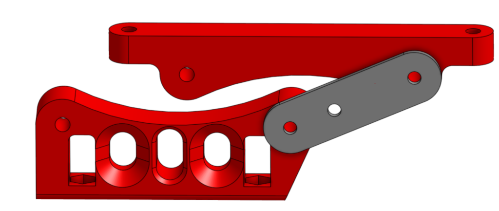
You may have noticed the switch in color of some parts from maroon to bright red; that is due to some iteration. The bright red parts are from before I made a change to the left pair of arms to use the same mounting as the right pair, while the maroon parts are from the final iteration. I apologize for any confusion, but I wished to explain the change and go into the design of both mounts. The original mounting for the left pair of arms had many flaws, and the spacing of the pivots on both sides similar enough that it made the most sense to use the right side lower mount for both sides.
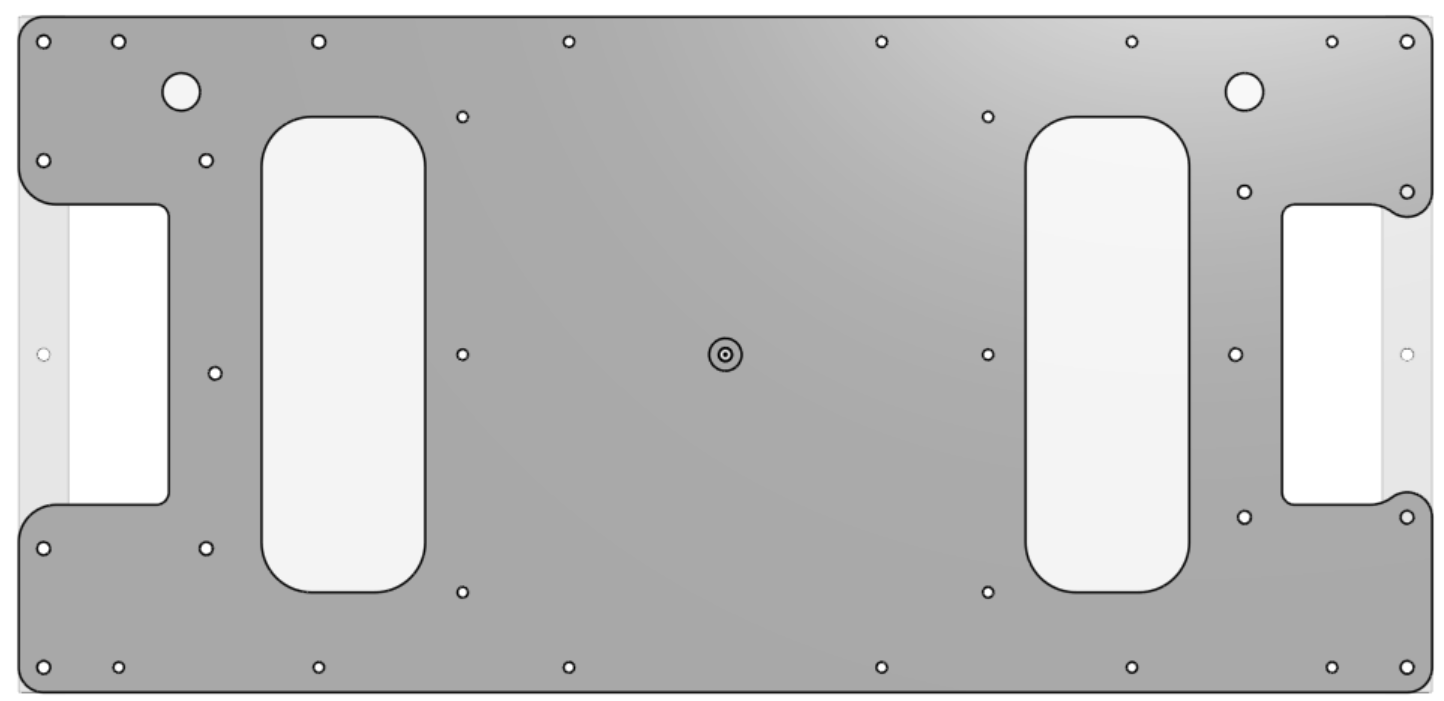
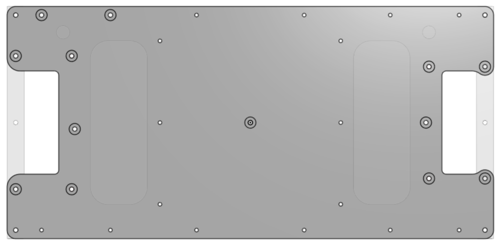
I designed the base of the station, shortly after the mounts, as a pair of plates with an aluminum backbone providing height and strength. The first of the pair of plates, which the mounts attach to, has a middle space where the laptop resides attached via Velcro strips. It also has two sets of cutouts; an outer pair to let the aluminum backbone serve as a handle and an inner pair to provide access to the space between the two plates, meant for items such as the laptop battery or cables. there are also many holes, mostly for mounting rivets but a couple in the corners wide enough for a USB to pass through for cable management.
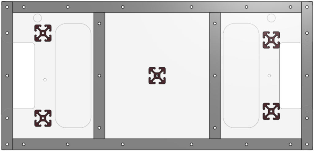
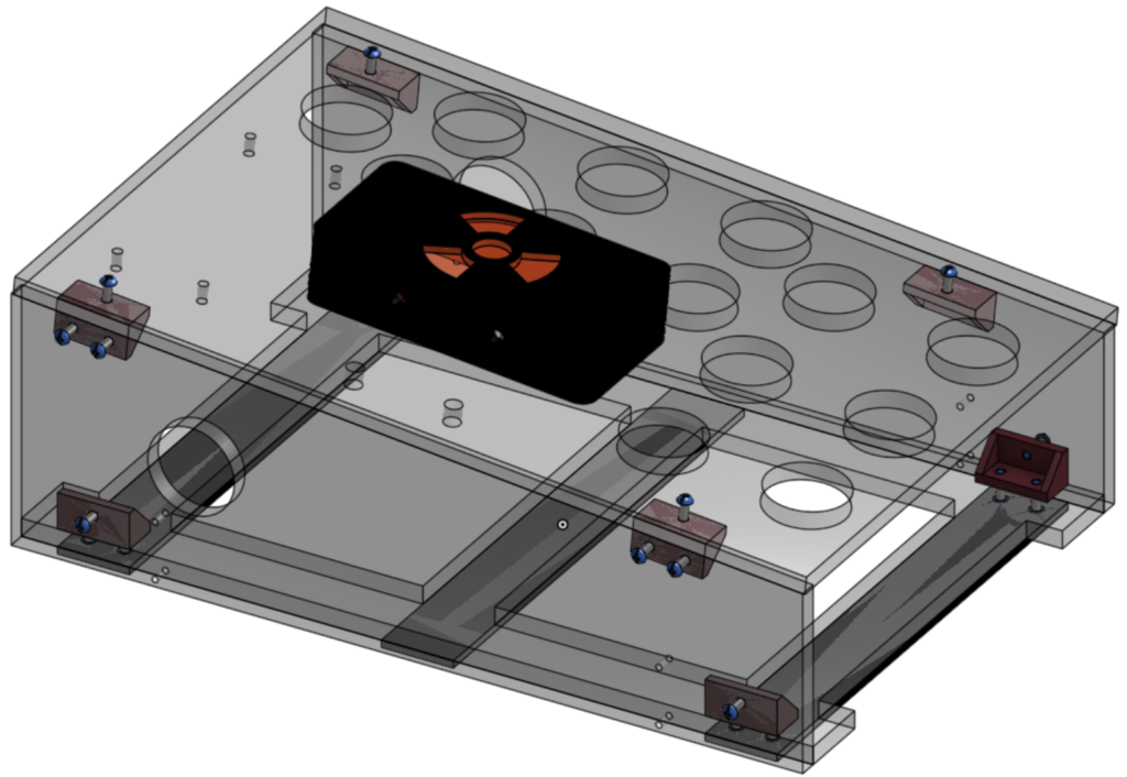
The aluminum backbone between the plates consists of a ladder structure, with 3D-printed 80-20 used as spacers to provide additional support. It was originally intended to be made of pieces of 1×1 box only connected by their connection to the top and bottom plates, however for strength I brazed it all. This structure provides the rigidity missing from the original design, while also providing convenient handholds on the ends. It does add considerably to the weight of the station, however the use of thin-wall aluminum over steel prevents it from getting too heavy.
The second of the pair of plates isn’t much to look at, but it serves key functions. One such function is to hold long strips of Velcro that secure the station when in use, ensuring that it stays in place both for the safety of the drivers and the safety of the station. Another function is to secure the 80-20 spacers, having inset pockets to prevent bolt heads from interfering with the Velcro while bolting the spacers, plates, and mounts together. Its last function is to prevent anything stored in the pockets between the plates from falling out.
I designed the control panels at around the same time as the mounts, as they factored into their placement. The right control panel, which is a programmable button panel, was simple. I had already redesigned it the year before to be more ergonomic, so all I had to do was some tweaking. I changed the bottom plate, which originally Velcroed onto the old driver station, to be sturdier and have mounting spots for the four bar linkage. The only change besides this one was to add receptacles for a sliding bolt that I added after initial testing of the station showed that the joystick control panel drooped when collapsed, not by bending but due to tolerance in its pivots. The receptacles and sliding bolts solved this, while also keeping the station more securely collapsed. On the left is the prior version of the button panel, while the right shows the modified version.
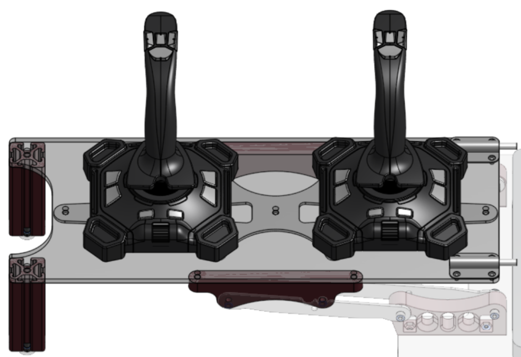
The joystick control panel was more challenging, but still pretty straightforward. I measured the total footprint of the joysticks and the placement of their mounting holes, then used those dimensions to space them comfortably apart; this determined the length of the plate. I also added the mounting holes for the four bar linkage, which gave the width of the plate. I added two bump-outs for supports to attach to, which were in the form of 3D-printed 80-20 extrusion. Since the station as a whole would likely be slightly taller or slightly shorter than in CAD, I made sure that the end of the supports were above the bottom plane and able to have 5/16″ bolts screw into them and adjust their height. This long plate would be made out of flexible polycarbonate, so to prevent it from flexing too much in use I designed an aluminum spine piece as a brace. The last additions to this assembly were the sliding bolts that dock with the other control panel for rigidity in transport.
This new driver station has now been used during many competitions, doing its job and being more convenient for the drivers. It has also been through extensive use in driving and testing robots outside of competition and even built by another team. The link to the CAD is here – 2052 KnightKrawler Driver Station