I use this CNC quite a bit, which means that there are quite a lot of chips flying around. After getting fed up with the mess, I started designing this dust shoe to minimize the amount of cleanup required after cutting. It is made completely out of 3D printed PETG – selected for its flexibility- plus thin face shield plastic acting as a brush.
Prototype 1
My first iteration on the dust shoe mounted to the spindle, for a couple reasons. The main reason was the model of CNC (OMIO X8 2200L) has no holes for mounting on the Z axis, so mounting on the spindle is easiest. A lower mounting spot also means using less material to reach the chi[s and less print time, making the project cheaper and faster to iterate. This second reason led me to start on a lower section of the spindle, which didn’t leave any room for adjusting for the height of the bit; it was stuck being slightly above the edge of the shortest bit, so that it could clear the material being cut.
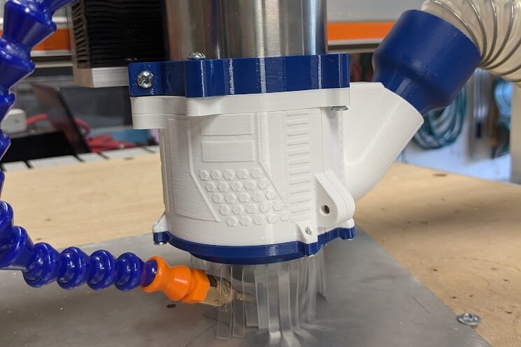
This prototype consists of a vacuum hose and 3 parts: the clamping spindle mount, the body, and the cover. The mount slides onto a lower section of the spindle then is secured by a bolt and locking nut, which allows the body to be bolted into it at two points; one has a slot in it to account for the bending of the mount as it is tightened. A vacuum hose can be slid into the body to provide chip suction after the body is attached. When in use, the cover can be snapped on and, when the bit needs to be changed or inspected, the cover can be pulled off without needing to raise the spindle. It attaches with press fit magnets, which I provided locations for 4 pairs of, but ended up only needing one pair per side.
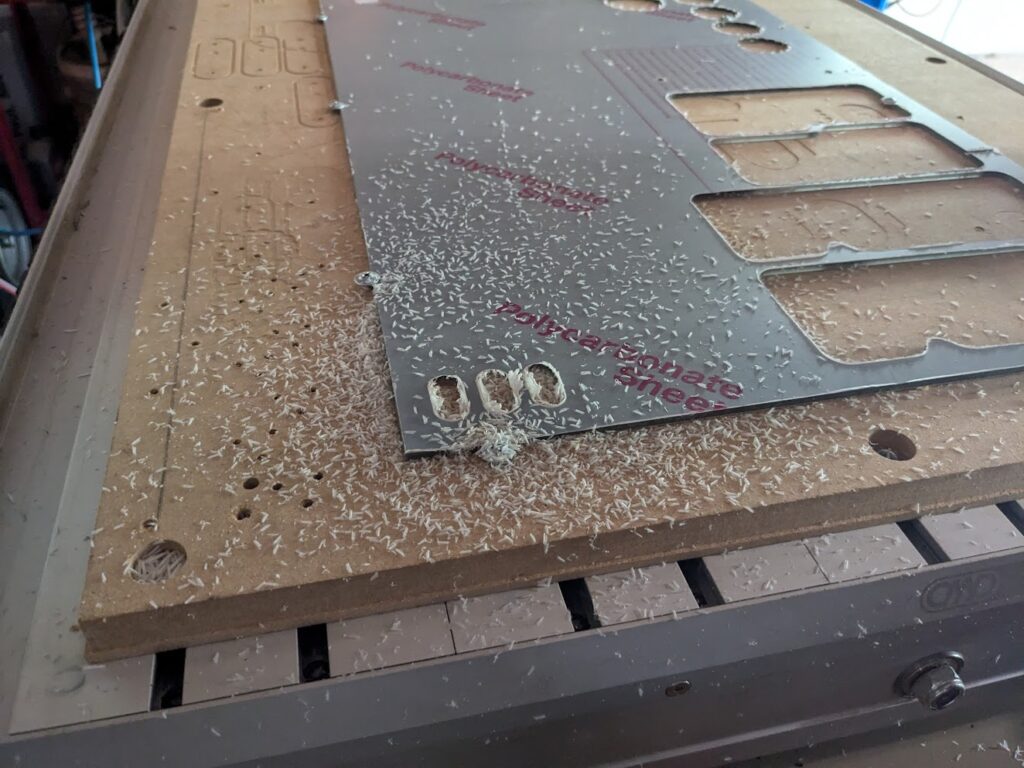
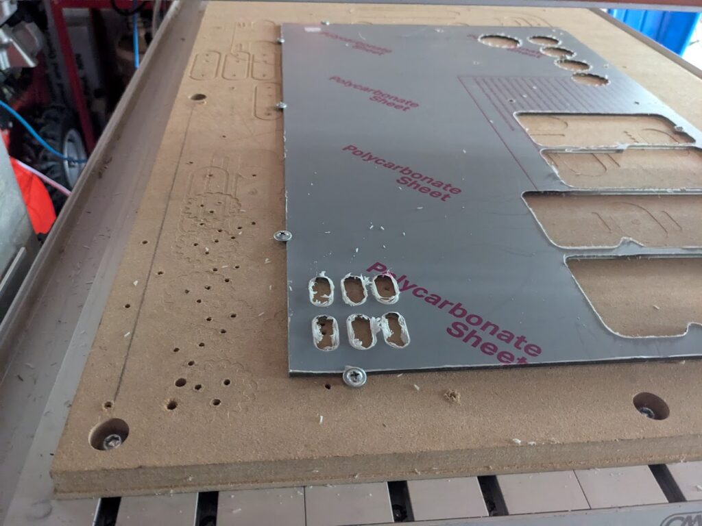
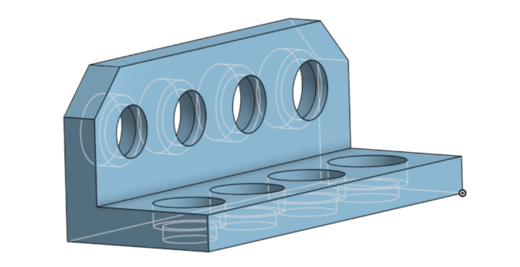
To test the prototype, I vacuumed off the waste board and programmed a pocketing operation that I used for both cuts, making sure to clear the waste board between them. The one on the left was after the control cut, where the shoe assembly was taken off. The one on the right was the test cut, with the shoe put on and vacuum running. It worked surprisingly well, but there were quirks and issues with using it to improve on.
One of the glaring issues of this prototype was the inability to adjust the height of the assembly. Only two bits that I cut with regularly are similar heights, and I often cut varying height stock, so the next shoe had to either be adjustable or had to have some way of quickly swapping them out. Another issue was that the cover was annoying to take off with bolts being in front of the magnets. Another issue was that the magnets were placed on the side of the cover, but not the top. This kept how the cover was held from being uniformly secure, which made it easier to knock off.
Prototype 2
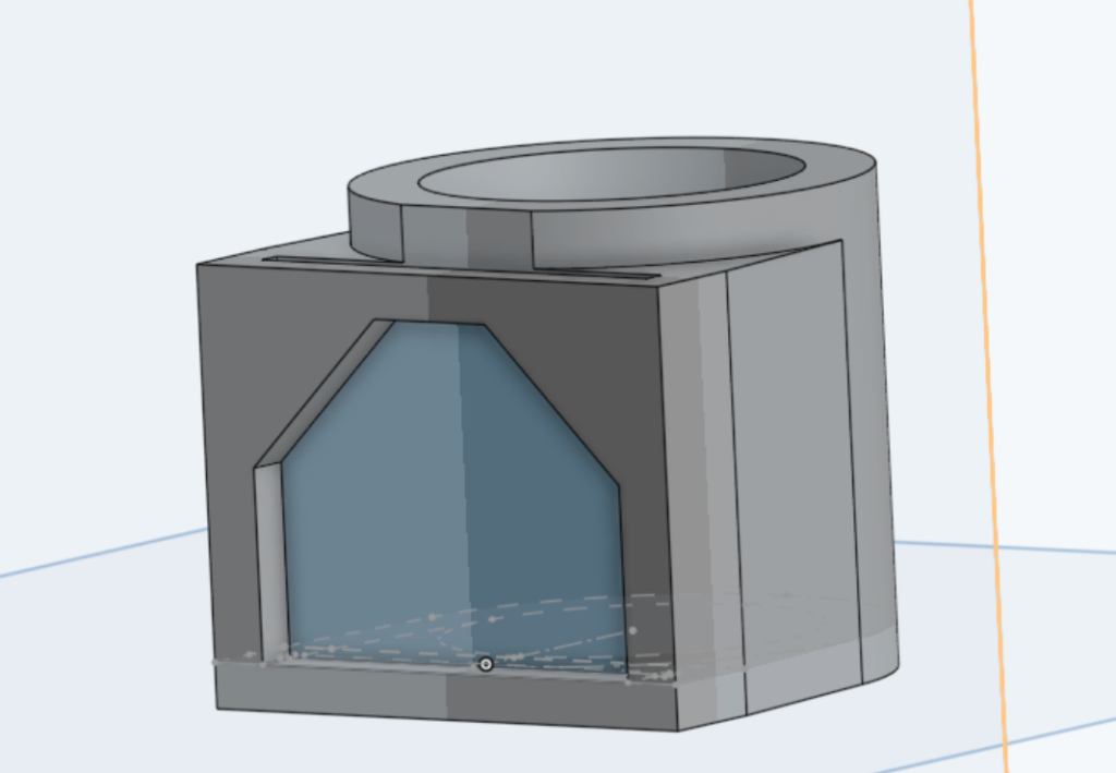
I forgot to take an actual picture of this iteration, but it mounted higher up on the spindle, allowing it to be moved up and down when the spindle mount is loosened. It consists of the same parts as the previous iteration, although redesigned from the spindle down. The cover/body have an additional place up top for a magnet for stronger attachment, while the whole assembly is taller to account for a higher mounting point. The cover also has a ring on the bottom to mimic the shape of a door seal brush, making the prototype less effective at testing cutting but more effective on doing a fit-test.
This prototype also had issues, like the fact it couldn’t effectively test how a brush at the bottom would act. Besides that minor issue, there were structural issues on the body. Since there was an extra magnet on the top, any bump on the cover would flex the top ring of the body and flex the assembly as a hole. This was due to having only two points attaching the body to the spindle and them both being on one side. Additionally, there was no way to view the spindle and important details such as seeing the bit snapping or chips welding to the cut before they clear it.
Prototype 3
Prior to creating the actual dust shoe, I designed a series of test prints for various new features. One of these tests was for tuning the fit on both vertical and horizontal magnet holes, as they were popping out on the previous version and had to be superglued in. Another was to test the fit of and see any change to suction power with a plastic window. The last was to tune the fit of the brush I would be using, which I would have future problems with.

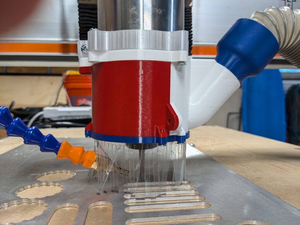
With these features worked out, I felt confident to print the next iteration. It was a modified version of Prototype 2 with an extra mounting hole between the body and spindle mount to be more secure along with a viewing window, a new vacuum hole for an existing hose model, holes to easily pop magnets out to replace them or remove at the end of the prototype’s use, and a slot to attach the brush. Using the brush ended up being an issue, as it would not easily bend. I couldn’t get it to a usable state, so instead it was suggested to create my own brush. I made this out of a roll of thin plastic cut into rectangles with strips cut out to form individual tines, then superglued a couple layers of this into the existing groove.
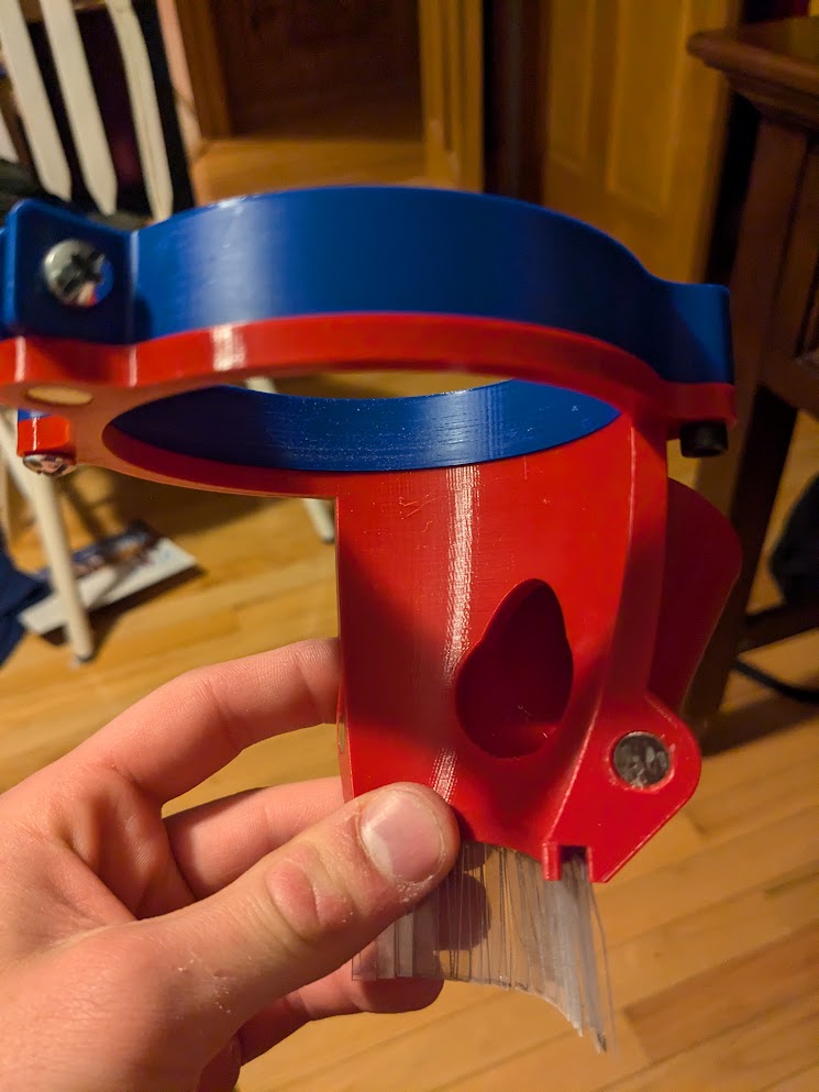
The improvised brush was effective, and solved a few problems. Since the material is transparent, it eliminated the need for a viewing window. This simplified the design and made it more effective, as the viewing window could only give a narrow and limited view of the bit. It also made it easy to adjust the height, as it could be pressed against the material being cut and form an effective seal unlike how previous models had to be safely above it.
Despite being a major success, this iteration also had its faults. one such fault was that the nozzle providing coolant to the bit was difficult to aim, being forced by the brush to be perpendicular to the bit at a set, ineffective location. Another issue was that the dust shoe could only be shifted so high up due to the curve on the inside forcing it apart as well as there being flex in the body at an unsecured point.
Prototype 4
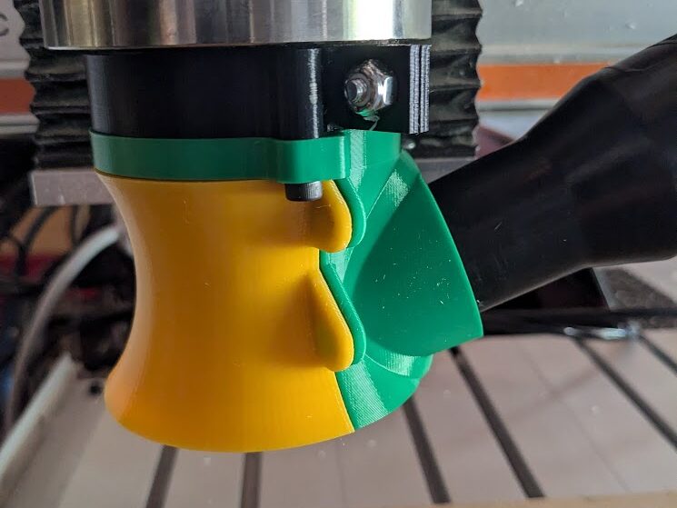
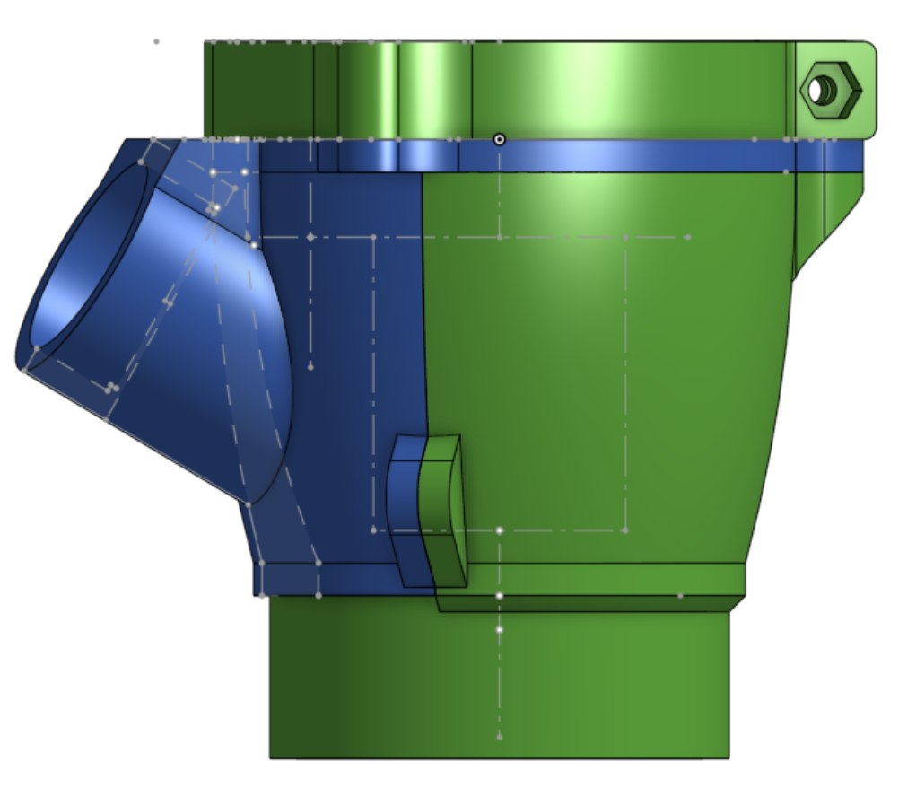
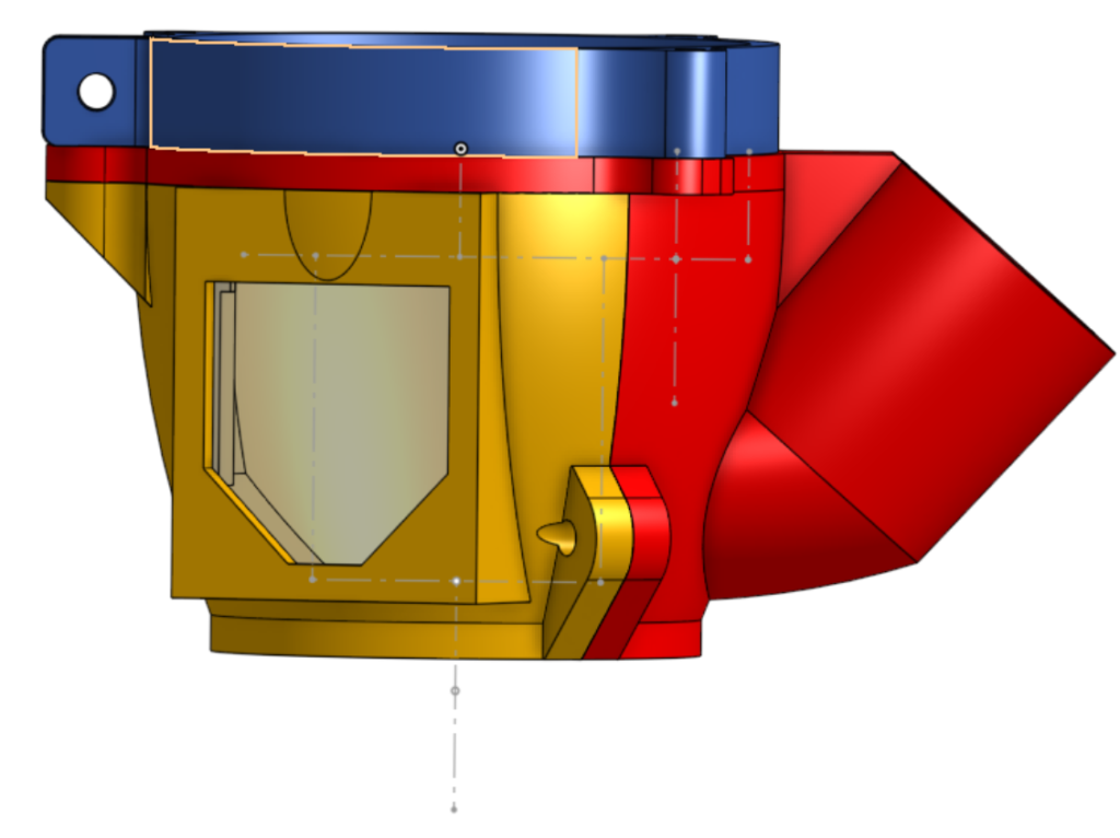
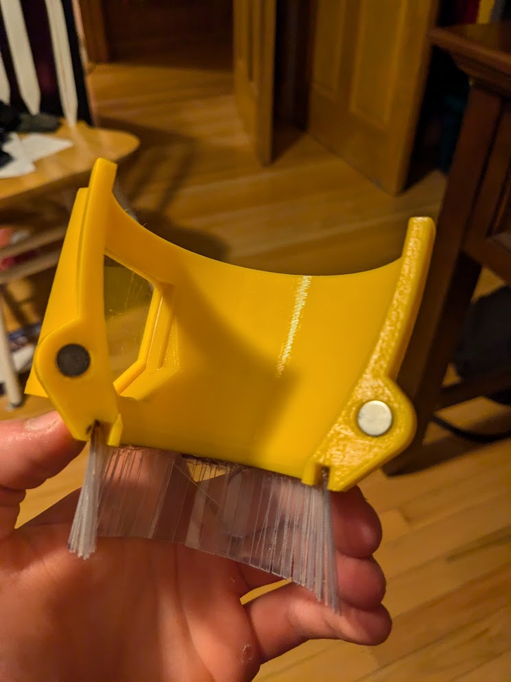
This prototype was designed from the ground up, focused on being able to slide from the top of the spindle to the bottom for maximum adjustment. It also has a longer, and replaceable, brush to speed up prototyping. The body also has an extra hole that doesn’t fully tighten, fully securing the body at four points on the Z axis but allowing the mount to be tightened or loosened still.
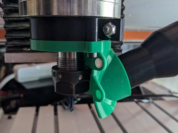
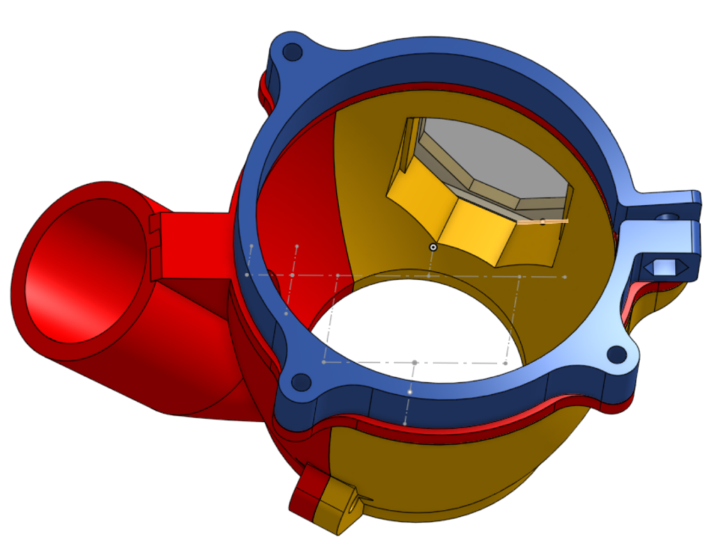
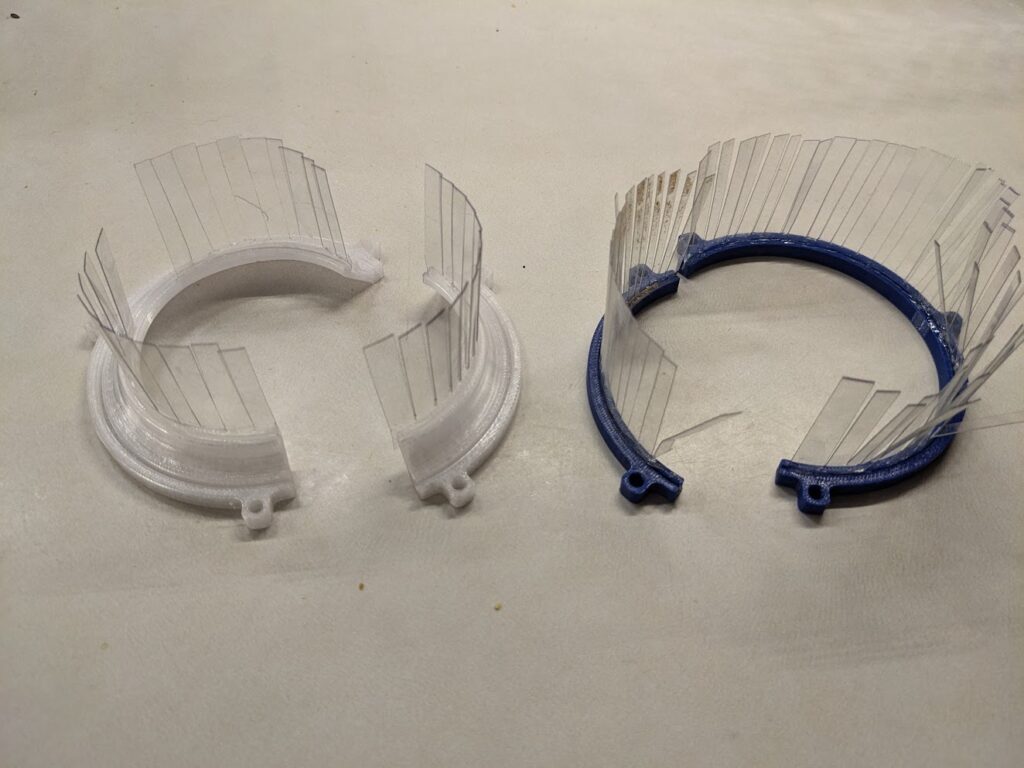
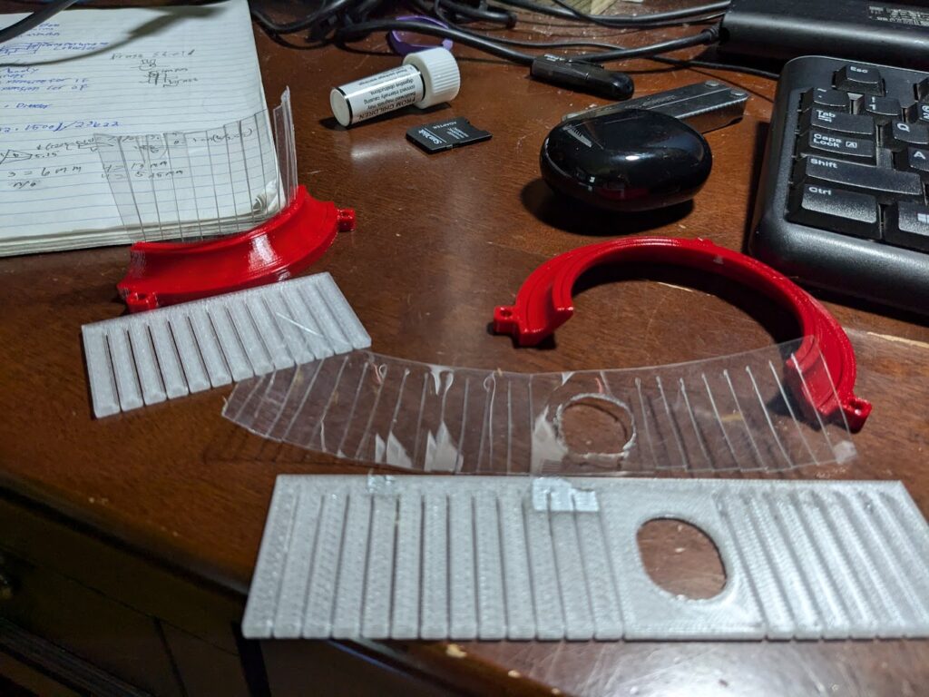
I went through a couple of iterations on the brush, originally a high-up and unbroken ring of brush; it was designed this way to accommodate a 2″ surfacing bit, which I used to determine the diameter of the more final brush design. I added a lower layer, which lowered the diameter of the hole that the vacuum sucked up and increased suction. Earlier brushes also had wider slots, but I tuned the width to allow for brush to be pressed in and not need to be superglued. This allowed replacement of damaged brushes and quicker installation. Another thing that I did with these brush holders is that I created jigs to more quickly and accurately cut new brush, making it easier to make different types of brush for different needs. I’ve found that using both the upper and lower layer of brush is most effective for catching material, especially on aluminum where I added a cutout in the brush to allow the nozzle to reach the bit. I can swap out brush-ends for plastics or wood when the coolant isn’t needed to prevent chips from flying through the cutout.
Version 5 Dust Shoe
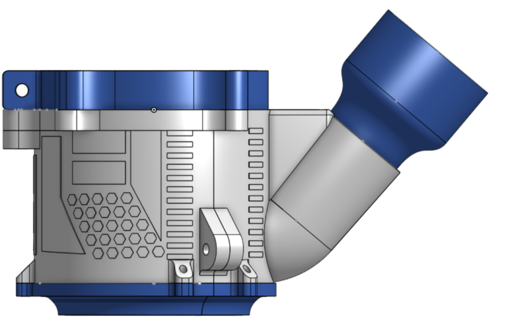
This dust shoe is almost identical to Prototype 4 except for some slight geometry tweaks and fun details on the side. The attachment points for the brush were moved slightly, and the model was cleaned up. It also has a flat edge in the back to reference when adjusting the dust shoe, intended to avoid any part of it rubbing on the Z axis. I would describe the effectiveness of the shoe at about 90% for plastics and wood, then 80% for light metals like aluminum.
I learned a good amount about designing for having vacuum suction, along with playing around with new tools in Onshape like the Wrap function or quirks with the “Up to Face” option for extrusions.
Link to the document – OMIO Dust Collection
Leave a Reply